
Apparatus for conditioning air

a technology of apparatus and air, applied in the field of apparatus, can solve the problems of less efficient boiling process, increased difficulty in removing residues, and decreased heat transfer rate to water

Inactive Publication Date: 2005-09-06
APPLIANCE DEVMENT
View PDF18 Cites 36 Cited by
  • Summary
  • Abstract
  • Description
  • Claims
  • Application Information

AI Technical Summary

Benefits of technology

"This patent describes various apparatuses with an immersible heater that can be easily cleaned. The technical effects of this invention include improved operation efficiency, easy cleaning, economical manufacturing, and improved user experience. Additionally, the patent describes a humidifier that can be easily cleaned and a water distilling apparatus that can also be easily cleaned. The patent also describes different configurations and arrangements of the apparatus to allow for easy installation and maintenance."

Problems solved by technology

As the residue accumulates, the heat transfer rate to the water decreases with two adverse effects.
First, the process by which the boiling occurs becomes less efficient.
Secondly, the heating coils operate at a higher temperature.
Moreover, as also known, the residue becomes more difficult to remove after it accumulates over time.
However, like the other devices described above, it is necessary to handle an entire base unit.
However, such heating elements are usually integral with a base unit and hard to reach.
Consequently, individuals do not clean such devices on a regular basis even though this means that the operating efficiency for the apparatus is degraded.
Prior apparatus, particularly prior humidifiers, have other operating deficiencies.
For example, a requirement to heat large volumes of water increases the time that lapses between the application of power to and the generation of steam by the humidifier.
Large volumes of water also can pose a risk if the humidifier tips and discharges hot water as all the water is heated and potentially injurious.
In others, the boiling process can cause spurts of hot water to eject from the humidifier causing proximate furniture or carpets to become soiled.

Method used


Image

  • Apparatus for conditioning air
  • Apparatus for conditioning air
  • Apparatus for conditioning air

Examples


Embodiment Construction

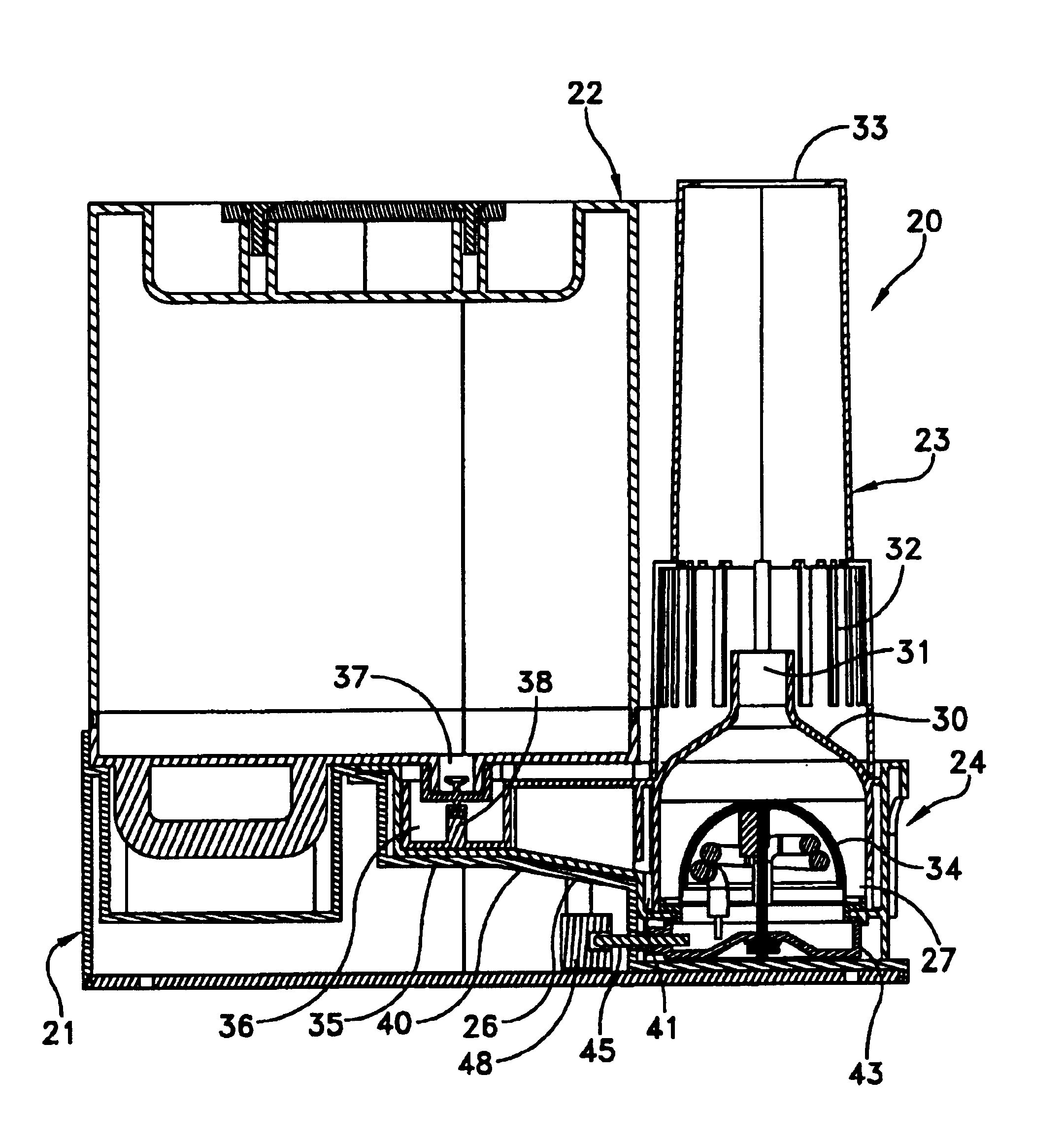
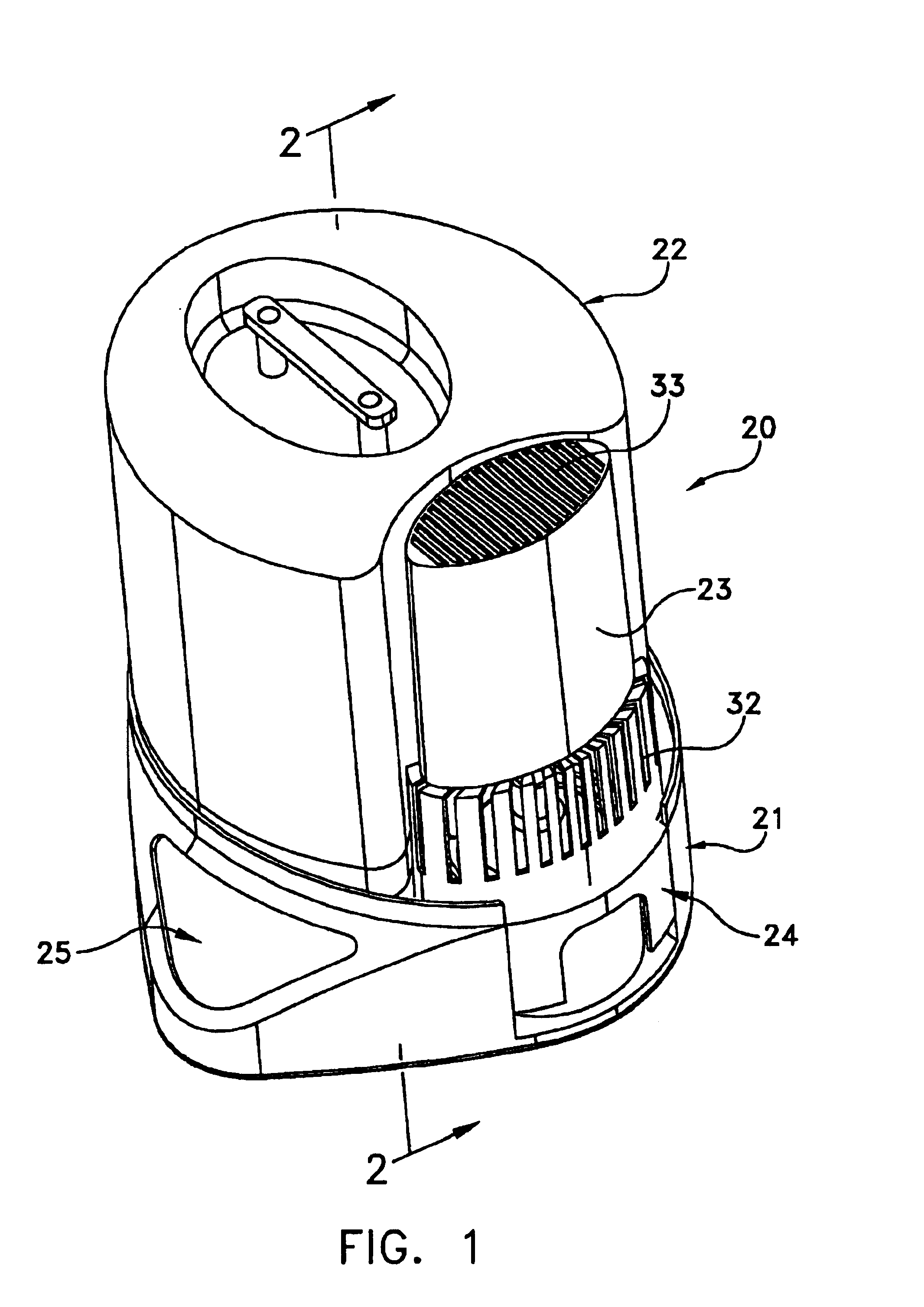
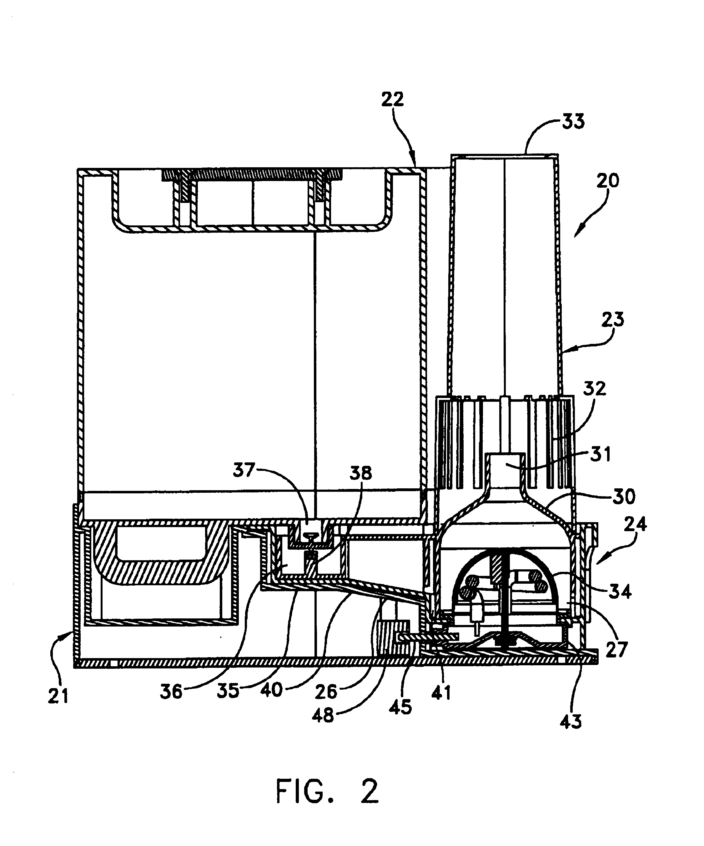
[0038]FIG. 1 depicts a first embodiment of warm mist humidifier 20. This particular warm mist humidifier includes a base unit 21, a water tank unit 22, a mixing stack 23 and a removable steam generator assembly 24. A control panel 25 includes an on / off switch, operating lights and other components (not shown) as necessary.

[0039]Referring to FIGS. 1 and 2, the removable steam generator assembly 24 includes a steam generator 26 that contains water collected in a boiling chamber 27 located within the confines of a generally cylindrically shaped steam dome or chimney 30 that also supports the mixing stack 23. As shown most clearly in FIG. 2, the steam dome or chimney 30 is removable and can be formed of a number of materials including a talc-filled polypropylene. The chimney 30 additionally includes an output 31 with a funnel shape that allows the steam to form a high velocity jet. As the jet moves vertically upward in FIG. 2, it provides an area of reduced pressure allowing room air to...


PUM

PropertyMeasurementUnit
resistanceaaaaaaaaaa
temperatureaaaaaaaaaa
boilingaaaaaaaaaa

Abstract

A humidifier including a steam generator with a container for water and an immersed heating module. The heating module has a spherical shape and is formed of a stainless steel outer surface and an aluminum inner body. Electrical heating coils are affixed to the aluminum body to heat the aluminum body and transfer heat through the stainless steel into water. The composite of the inner and outer bodies provides efficient heat transfer for boiling water. The stainless steel resists any permanent adherence of residue to the heating module during the boiling process. Steam from the boiling water transfers through a mixing stack to surrounding air in the humidifier.

Description

CROSS REFERENCE TO RELATED APPLICATION[0001]This application is a continuation-in-part of my application Ser. No. 09 / 571,351 filed May 16, 2000 for Apparatus for Humidifying Air Distilling Water (now abandoned).BACKGROUND OF THE INVENTION[0002]1. Field of the Invention[0003]This invention generally relates to apparatus that can be used to humidify air and more specifically to apparatus that uses an immersion heater for converting liquids into gas as, for example, by generating steam for use in humidifiers.[0004]2. Description of Related Art[0005]Humidifiers, distilling apparatus and like apparatus use immersion heaters to convert a liquid, such as water, into vapor or steam by boiling water. In humidifiers the steam mixes with air and disperses throughout a room to increase relative humidity. In a distilling apparatus a condenser receives the steam to produce distilled water.[0006]There are many embodiments of such apparatus. Generally, however, warm mist humidifiers and distilling ...

Claims


Application Information

Patent Timeline
Patent Type & Authority Patents(United States)
IPC IPC(8): F22B1/00F24F6/18F22B1/28
CPCF22B1/284F24F6/18Y10S261/10
Inventor GLUCKSMAN, DOV Z.
Owner APPLIANCE DEVMENT
Learn More