
Method for verifying functional integrity of computer hardware, particularly data storage devices

a technology for computer hardware and functional integrity, applied in the field of data storage devices, can solve problems such as unreliable components or and unreliable one or more components along the data path

Inactive Publication Date: 2005-08-30
QUANTUM CORP
View PDF11 Cites 51 Cited by
  • Summary
  • Abstract
  • Description
  • Claims
  • Application Information

AI Technical Summary

Benefits of technology

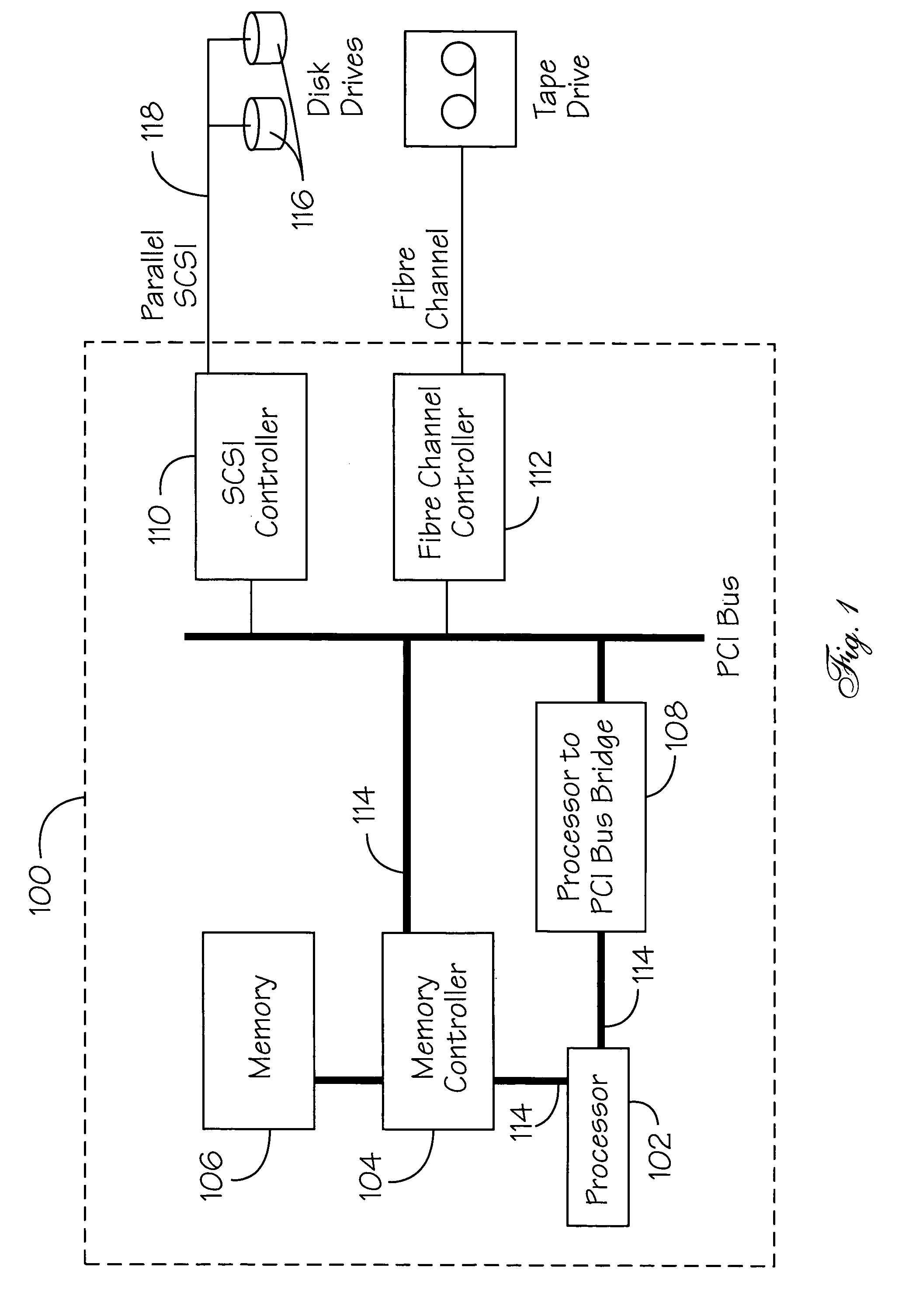
[0022]The processor can also perform tests to confirm the integrity of the I / O controllers. The processor may issue instructions to the fibre channel controller and the SCSI controller which will cause the controllers to read the pattern data from the memory into the controller's local buffer space and then to copy the pattern data back into the memory. The processor may then compare the copied data to the original pattern to determine if an error occurred during the data transfers. If no error occurred, then the test has determined that the data paths through the I / O controllers, the PCI bus and the memory controller are reliable. If an error is detected, however, then one or more components along the data path are unreliable and the system can take any necessary actions to prevent further data flow through those components.

Problems solved by technology

The DPT method is further designed to operate in an open system, where the components in use are “off-the-shelf”, and do not provide any specific hardware support for data checking.
If an error is detected, however, then some component or components along the data path is unreliable and the system can take whatever actions are necessary to prevent any further data flow through the failing component(s).
If an error is detected, however, then one or more components along the data path are unreliable and the system can take any necessary actions to prevent further data flow through those components.

Method used


Image

  • Method for verifying functional integrity of computer hardware, particularly data storage devices
  • Method for verifying functional integrity of computer hardware, particularly data storage devices
  • Method for verifying functional integrity of computer hardware, particularly data storage devices

Examples


Embodiment Construction

[0028]Generally speaking, the invention features a method for evaluating the end-to-end integrity of a data path in a computer and, more specifically, in devices such as storage routers.

[0029]The Data Path Test (DTP) method of the invention is a set of hardware independent procedures that allows testing of every component along a data path from a data initiator to a data receiver. Because there is no hardware dependence, the inventive DPT method is usable in open systems environments where the hardware components along a data path may be provided by several different vendors. FIG. 3 is a flow chart of the steps of the inventive DTP method. The flow chart of FIG. 3 describes a generic implementation of the inventive DPT method. First a data test pattern is generated, step 302, and stored in memory, step 304. The pattern in memory is transmitted by the data initiator, step 306 and received at a data receiver, step 308. The received pattern is then re-transmitted, step 310 from the dat...


PUM


Abstract

The present invention features a method for performing an end-to-end data path integrity check in a computer or computer-like system such as a storage router. A predetermined data test pattern is stored in a memory and then transmitted across a data path by a data initiator to a data receiver. The received data test pattern is then retransmitted to the data initiator where it is compared to the original data. Any discrepancies cause an error condition to be declared. The data path may be disabled until the defective component in the data path is isolated and fixed. The method is hardware independent so it may be easily used in an open systems environment where hardware components may be provided by different vendors.

Description

FIELD OF THE INVENTION[0001]This invention pertains to diagnostic testing of computer hardware and, more particularly, to a method for periodically testing the data path integrity between data storage interfaces and internal buffer memory.BACKGROUND OF THE INVENTION[0002]It is common in computer systems to perform diagnostic tests when a system is started (i.e., booted). Faults detected at that time result in the system being placed in an error state. The computer, therefore, cannot be started without user intervention.[0003]It is also common in computer systems to monitor system components during normal operation to detect errors that may occur during normal operations. For example, parity is generated and subsequently checked as data is transmitted across data buses or when data is sent to a data storage device. Typically, any other diagnostic testing during normal system operation requires user intervention to specifically execute a diagnostic task. Also typically, these diagnost...

Claims


Application Information

Patent Timeline
Patent Type & Authority Patents(United States)
IPC IPC(8): G06F11/00G06F11/267
CPCG06F11/221
Inventor KELLEHER, TERENCE M.
Owner QUANTUM CORP
Learn More