
Power generating controller of a vehicle

a technology of power generating controller and vehicle, which is applied in the direction of machines/engines, vehicle sub-unit features, electric devices, etc., can solve the problems of increasing fuel consumption, not being positively utilized, and decelerating energy during deceleration in which fuel is not required, so as to reduce fuel consumption, reduce power required, and improve the efficiency of generative operation of the generator

Inactive Publication Date: 2005-08-30
SUZUKI MOTOR CORP +1
View PDF30 Cites 24 Cited by
  • Summary
  • Abstract
  • Description
  • Claims
  • Application Information

AI Technical Summary

Benefits of technology

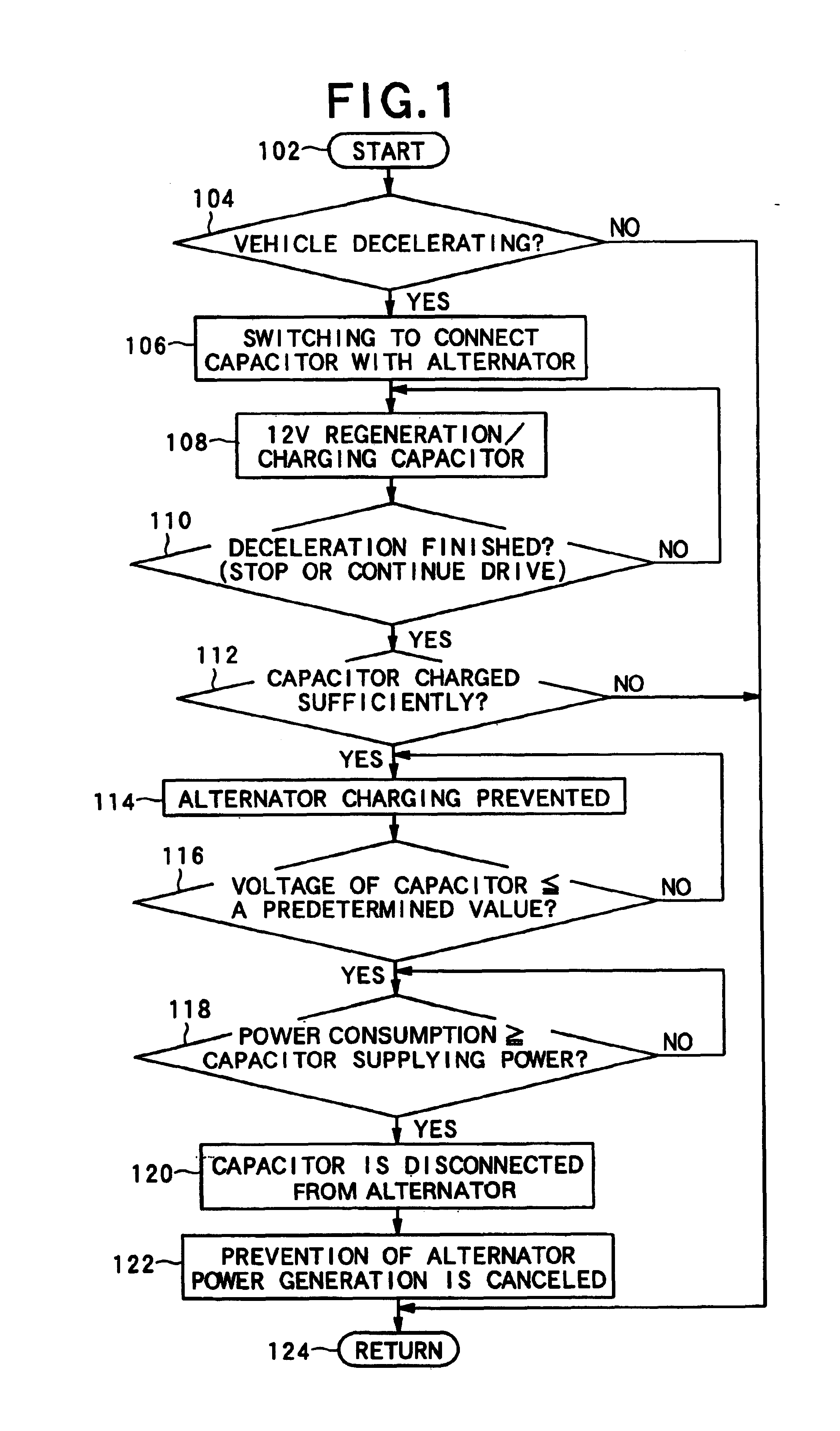
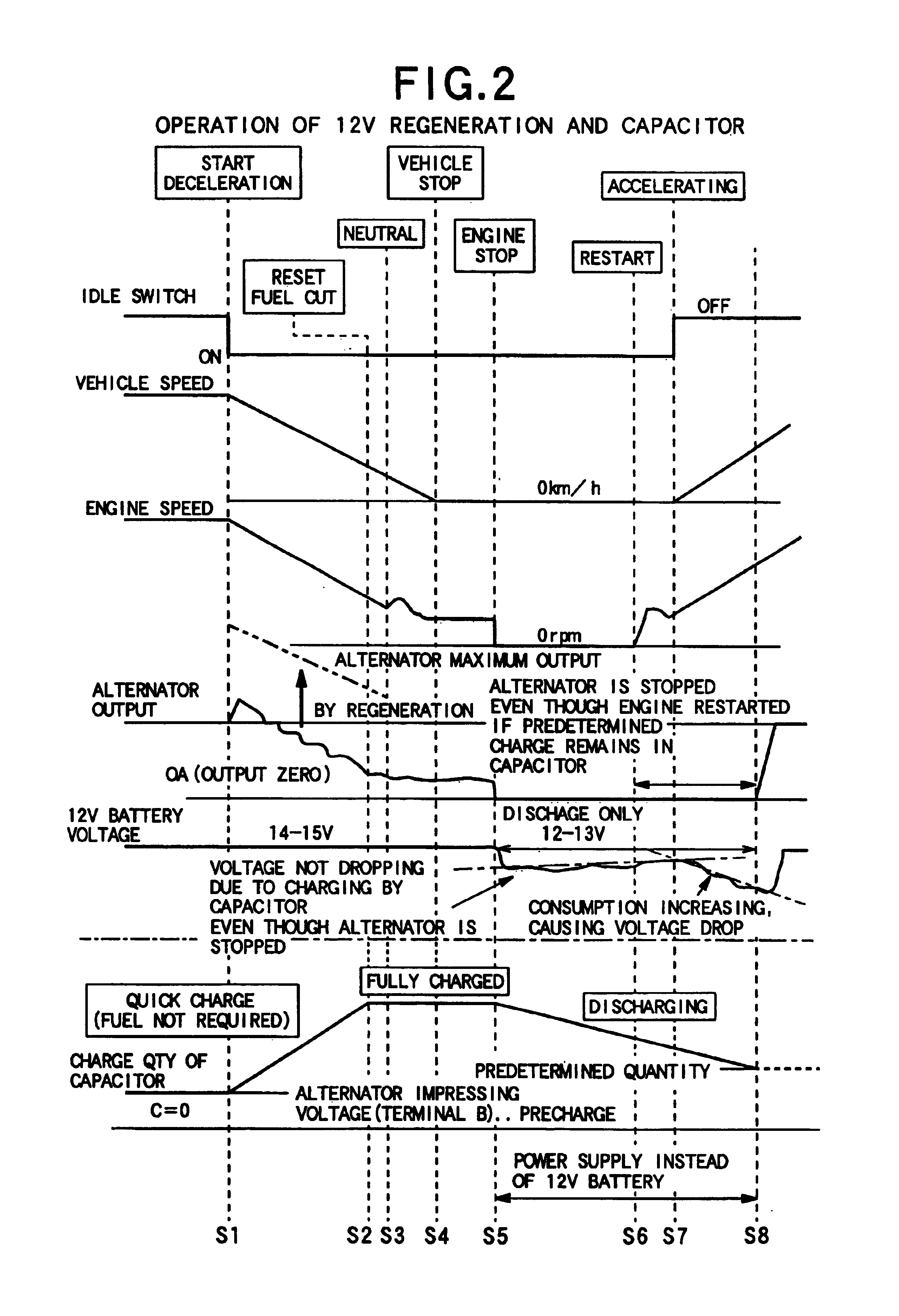
[0009]The present invention provides such a controller to make a connection between the generator and the second power supply when the vehicle is decelerating or when a charge quantity of the second power supply is greater than a predetermined value, which charges the second power supply while the vehicle is decelerating. Accordingly, the second power supply can be utilized as a power supply for electric loads (maintenance for the engine controller system or lamps and the like) when the engine is stopped after the vehicle is stopped (vehicle with the automatic stop / start-up system), or when the charge quantity of the second power supply is greater than a predetermined value. Thereby, the electric power of the first power supply, which is used at startup or during vehicle driving can be conserved, which can reduce power required for charging of the fist power supply, so that engine load by operation of the generator can be reduced to decrease fuel consumption. In addition, deceleration energy which has not been utilized conventionally can be recovered to the second power supply, which allows use of power generation (regeneration) during deceleration of the vehicle, in which fuel is not required, to improve efficiency of generative operation of the generator.

Problems solved by technology

However, in a conventional vehicle, the alternator which is a generator driven by the engine, is driven as a part of the engine load, which increases fuel consumption, which is disadvantageous from an economical view point.
On the other hand, deceleration energy during deceleration in which fuel is not required, has not been positively utilized and improvement thereof has been desired.

Method used


Image

  • Power generating controller of a vehicle
  • Power generating controller of a vehicle
  • Power generating controller of a vehicle

Examples


first embodiment

[0021]The present invention will now be described in specific detail with reference to FIGS. 1-7, which illustrate the invention. Referring to FIG. 7, a vehicle 2 includes an engine 4, a transmission 6, a clutch 8 disposed between the engine 4 and the transmission 6, an alternator (ALT) 10 for a 12 volt battery system generating electricity from driving of the engine 2, and an engine controller 12 for controlling the operating state of the engine 4. The engine controller 12 comprises an engine control means 14 connected with the engine 4, an automatic stop / startup system (idle stop system) 16, and a fuel cut (F / C) system 18.

[0022]The engine 4 is automatically stopped by the engine control means 14 when a predetermined automatic stop condition, such as a control of the automatic stop / start-up system 16, is satisfied while the engine 4 is idling, and the engine 4 is automatically started when a predetermined automatic startup condition is satisfied while the engine is stopped. In addi...

second embodiment

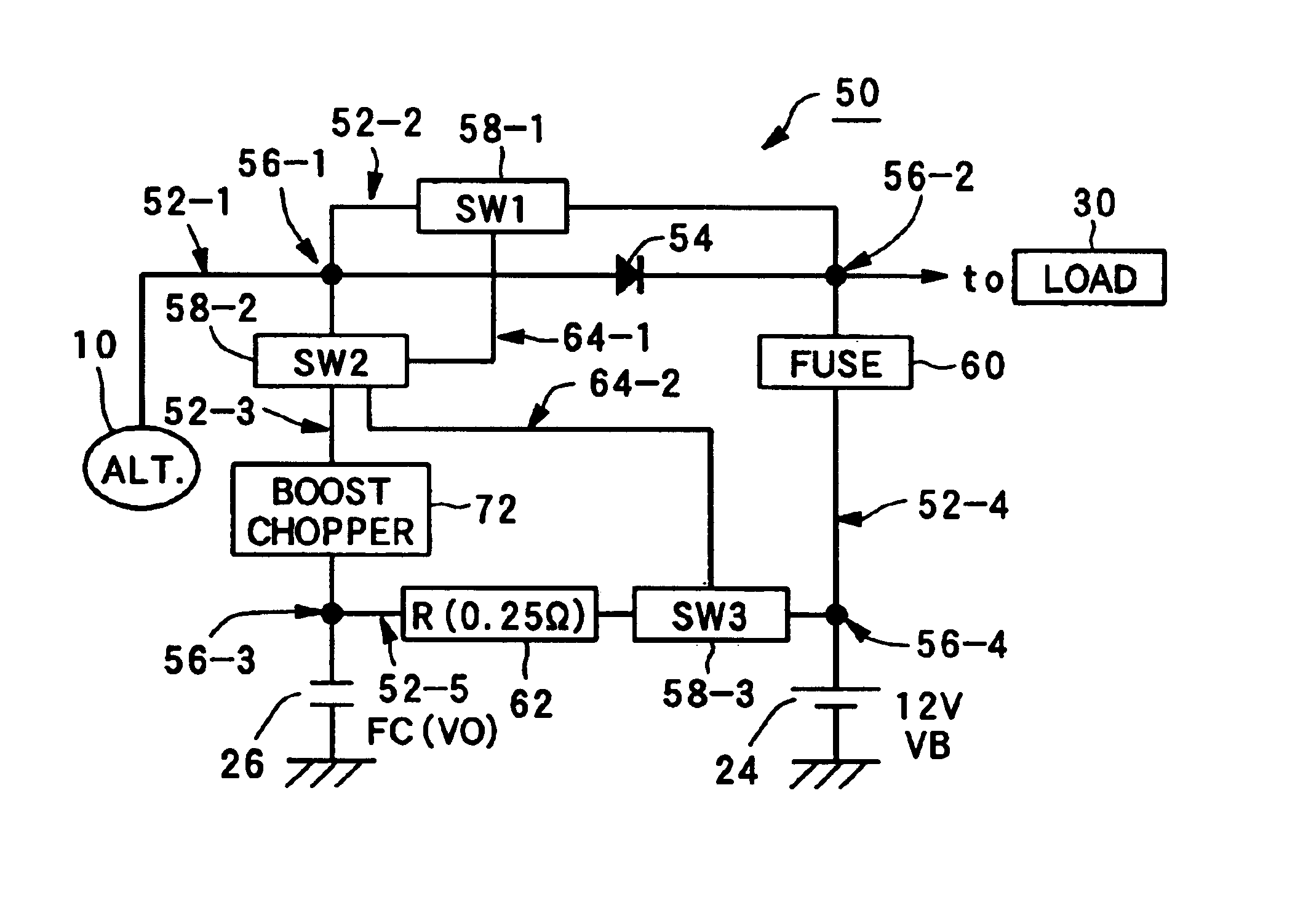
[0081]The second embodiment is characterized in that the battery 24 and the electric load 30 are not disconnected in the charging circuit 50 having alternator 10 as shown in FIG. 8 and that a boost chopper 72 is disposed on the third signal line 52-3 between the second switch 58-2 and the third node 56-3.

[0082]As shown in FIG. 9, each of the switches 58-1, 58-2, 58-3 interlocks as in FIG. 5 of the first embodiment. Turning of the first switch 58-1“ON” turns the second switch 58-2“OFF”, and vice versa. Turning of the third switch 58-3“ON” turns the second switch 58-2“OFF”. When voltage is impressed (precharged) at the third terminal 38-3 (B) of the alternator 10 during charging of the capacitor 26, then the first switch 58-1 is turned on, the second switch 58-2 off, and the third switch 58-3 on. In a normal operation, the first switch 58-1 is turned on, the second switch 58-2 off, and the third switch 58-3 off. Furthermore, while charging (regenerating) during deceleration, or when t...

third embodiment

[0084]FIG. 11 illustrates the present invention.

[0085]The third embodiment is characterized in that the vehicle comprises a hybrid vehicle 2A. The hybrid vehicle 2A comprises an alternator 10 as a first generator for engine 4 and a motor generator (motor) 82 as a second generator between the engine 4 and a clutch 8. The motor generator 82 is directly connected to the output shaft (not shown) of the engine 4, and has driving and generating functions, and is controlled by the motor control means 84 of the engine controller 12.

[0086]According to the third embodiment, as in the first embodiment, when vehicle 2A is decelerating or when charge quantity of the second power supply capacitor 26 is greater than a predetermined value, the second power supply capacitor 26 is connected with the alternator 10 and / or with the motor generator 82, thereby charging the capacitor 26 sufficiently during deceleration of vehicle 2. The capacitor 26 can be employed for engine load 30 (such as an engine co...


PUM


Abstract

In a power generating controller of a vehicle, electric power of a first power supply, employed at engine startup and during vehicle driving, is conserved to decrease power needed for charging of the first power supply and to reduce engine load by operation of a generator. In addition, deceleration energy, which has not been utilized conventionally, can be recovered to a second power supply, which enables use of power generation (regeneration) during deceleration of the vehicle, during which fuel is not required, to improve efficiency of the generative operation of the generator.

Description

RELATED APPLICATIONS[0001]This application is related to U.S. patent application Ser. No. 09 / 851,914 filed May 9, 2001, which is hereby incorporated by reference.FIELD OF THE INVENTION[0002]This invention relates to a power generating controller of a vehicle to recover deceleration energy during deceleration of the vehicle, when fuel is not required.BACKGROUND OF THE INVENTION[0003]Vehicles generally have an alternator which is a generator driven by an engine to supply power for the electric loads of an engine controller and other electric loads, such as a fuel injection system, lamps, blinkers, blower, wiper, air conditioner and the like. The alternator also is driven by the engine to charge, for example, a 12 volt vehicle battery at the same time.[0004]Among vehicles there are so-called hybrid vehicles provided with an internal combustion engine driven by combustion of fuel, the engine being provided with a motor generator (motor) driven by electric energy and having a power gener...

Claims


Application Information

Patent Timeline
Patent Type & Authority Patents(United States)
IPC IPC(8): B60K6/04B60K6/00H02J7/14B60K6/20B60K25/00B60K6/28B60K6/485B60K6/54B60L7/14B60L11/18B60L50/16B60W10/08B60W10/26B60W20/00F02D17/00F02D29/02F02D29/06F02N11/04F02N15/00H02J7/00
CPCB60K6/28B60K6/54B60L3/0046B60L11/005B60L11/14B60W10/08B60W10/26H02J7/1423H02J7/1446B60K6/485Y02T10/70B60L2210/40B60L2270/20Y02T10/6278Y02T10/7005Y02T10/7022Y02T10/7077Y02T10/92Y02T10/7241Y02T10/6226B60Y2400/112B60Y2400/114B60L50/40B60L50/16Y02T10/62Y02T10/7072Y02T10/72
Inventor MORIMOTO, KAZUHIKOOMATA, YOSHIAKI
Owner SUZUKI MOTOR CORP
Learn More