
Debugging apparatus and method

a debugging apparatus and a technology of a debugging device, applied in the field of debugging apparatus and methods, can solve the problems of not being able to recognize a data flow according to a data memory, taking a lot of time and expense for debugging, and wasting time and expense in performing a debugging operation. , to achieve the effect of saving time and expense in performing a debugging operation

Inactive Publication Date: 2005-08-23
LG ELECTRONICS INC
View PDF3 Cites 19 Cited by
  • Summary
  • Abstract
  • Description
  • Claims
  • Application Information

AI Technical Summary

Benefits of technology

[0017]Therefore, an object of the present invention is to provide a debugging apparatus and method that is capable of saving time and expense in performing a debugging operation by recognizing a data transition state in a specific data memory by observing a change of a data address and a change of data at the specific address in data memory.

Problems solved by technology

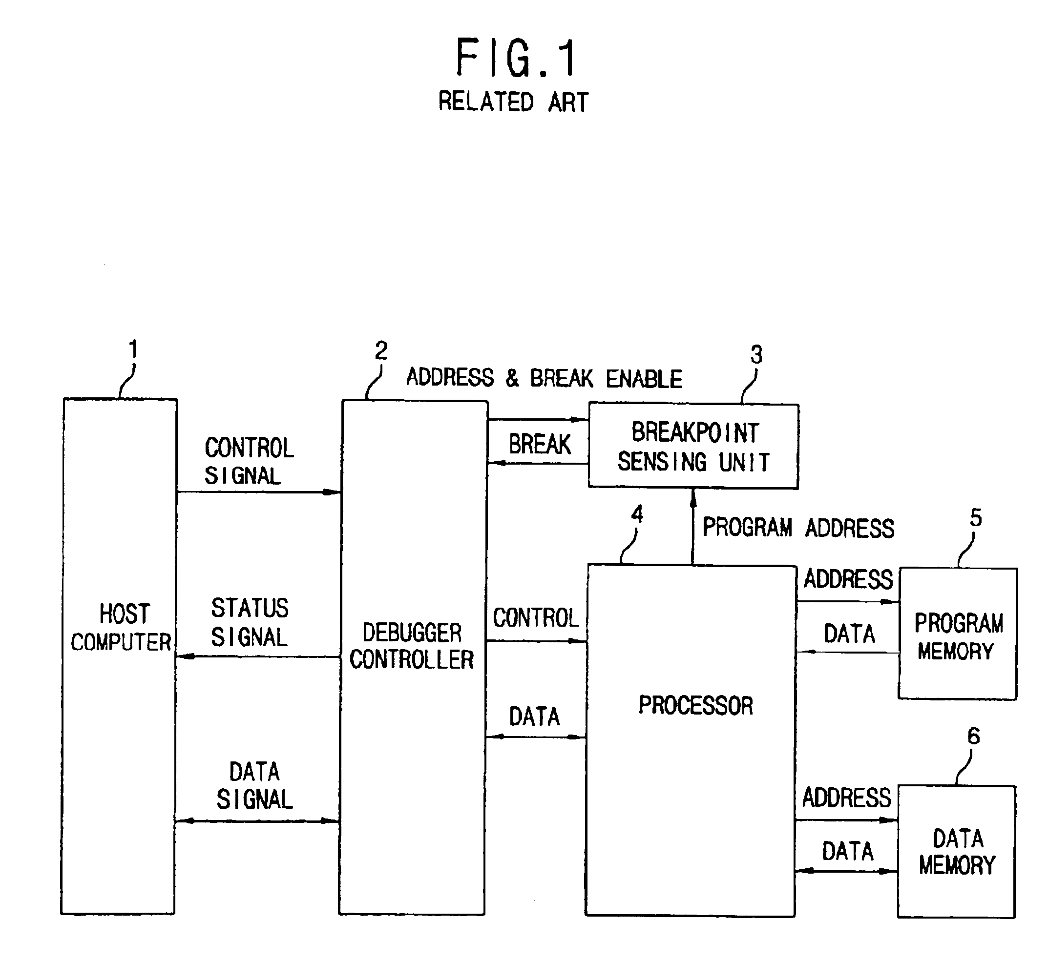
However, in the debugging method, since an operation is determined by an address of a specific program memory among the sequential programs, it is not possible to recognize a data flow according to a data memory.
Thus, in case where an error occurs by data, much time and expense is taken for debugging.
In addition, when creating a program, since the state of data is not recognized, an error may occur in the allocation of data memory.
In addition, if the wrong data is read in a calculating process, an erroneous result is output and may cause a system malfunction.

Method used


Image

  • Debugging apparatus and method
  • Debugging apparatus and method
  • Debugging apparatus and method

Examples


Embodiment Construction

[0028]Reference will now be made in detail to the preferred embodiments of the present invention, examples of which are illustrated in the accompanying drawings.

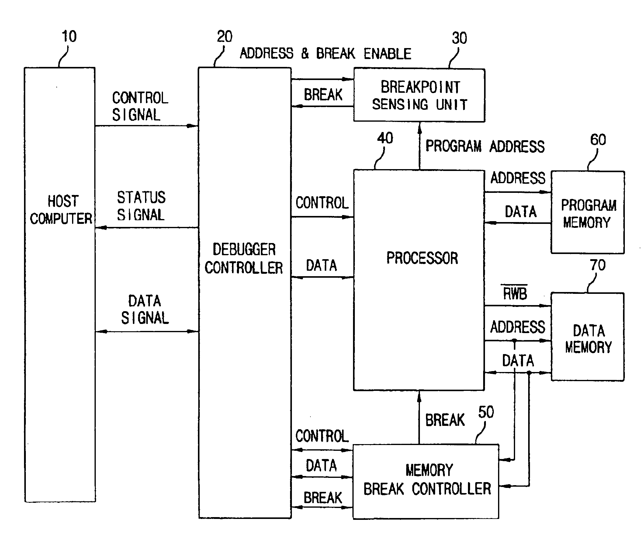
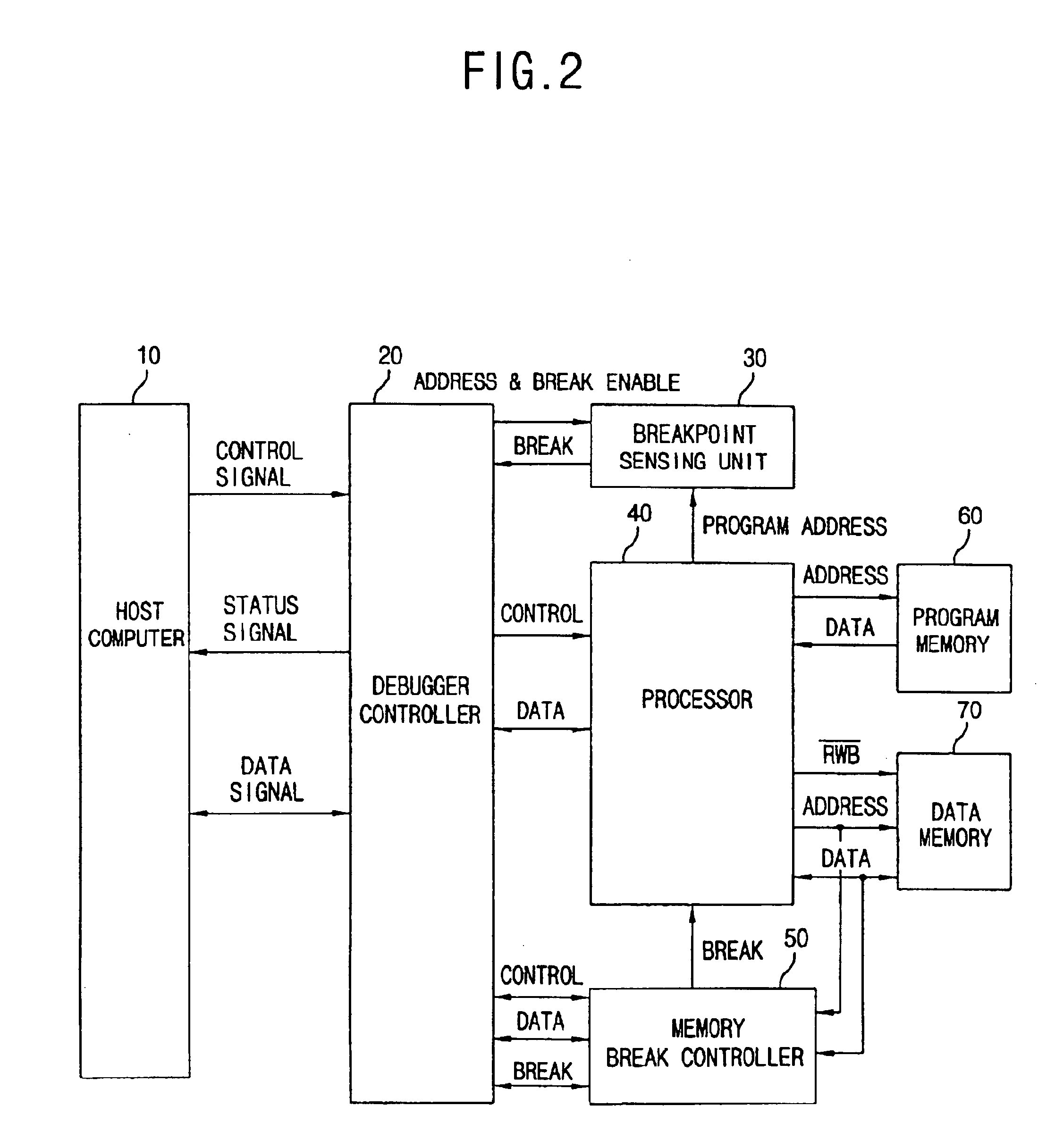
[0029]FIG. 2 is a schematic block diagram showing a debugging apparatus in accordance with a preferred embodiment of the present invention.

[0030]As shown in FIG. 2, a debugging apparatus of the present invention includes a host computer 10 for assigning a break point address and controlling a debugging operation; a debugger controller 20 for outputting a control signal to control a processor, a break point address and a break enable signal; a program memory 60 for storing a program to operate a processor 40; a processor 40 operated according to the control signal output from the debugger controller 20 and the program stored in the program memory; a data memory 70 for storing data output from the processor 40; a break point sensing unit 30 for observing an address of the program memory 60 accessed by the processor 40, recogni...


PUM


Abstract

A debugging apparatus includes: a processor core operated by a program stored in a program memory to read a data stored in a data memory or write a data; a debugger controller for performing a debugging on the processor core upon receipt of a command from a host computer and outputting a data break point address; and a memory break controller for observing an address of a data memory used by the processor core, recognizing an address as a break point address to output a break signal to the debugger controller and the processor core to suspend the operation of the processor core, when the address is sensed to be identical, and transmitting a corresponding address and data to the host computer through the debugger controller. Since an address and a data of a specific data memory are monitored to recognize a data flow and change of the specific address, an error that an erroneous calculation is inputted a during processing or a data memory is erroneously assigned is quickly sensed. Thus, a time and an expense for a debugging operation can be much saved. In addition, by adding a data debugging method to the conventional program debugging method, a program development environment is set similar to an environment substantially operated by the processor. Thus, a time and an expense for developing a program can be also saved.

Description

BACKGROUND OF THE INVENTION[0001]1. Field of the Invention[0002]The present invention relates to a debugging apparatus and method, and more particularly, to a debugging apparatus and method that is capable of recognizing a data conversion in a specific memory location by observing a change and flow of specific data memory location and performing a debugging process.[0003]2. Description of the Background Art[0004]In general, a debugging apparatus for detecting an error generated in a program input to a microprocessor includes a host computer and a microprocessor unit (MPU).[0005]In the debugging apparatus, when the host computer selects a specific address of program memory in the MPU as a break point, the MPU monitors the processor while the processor is being operated and when the specific address of the program memory accessed is identical to the memory address selected as the break point, the MPU recognizes the selected memory address as a break point and discontinues the operatio...

Claims


Application Information

Patent Timeline
Patent Type & Authority Patents(United States)
IPC IPC(8): G06F11/36G06F11/28
CPCG06F11/3636G06F11/28
Inventor OK, JAE CHUL
Owner LG ELECTRONICS INC
Learn More