
Control apparatus for hybrid vehicle

a control apparatus and hybrid technology, applied in special data processing applications, reciprocating piston engines, gas pressure propulsion mountings, etc., can solve the problems of reduced electrical energy that can be guaranteed by regeneration, reduced efficiency of transmission system, and limited assistance of electric motors

Inactive Publication Date: 2005-08-23
HONDA MOTOR CO LTD
View PDF4 Cites 28 Cited by
  • Summary
  • Abstract
  • Description
  • Claims
  • Application Information

AI Technical Summary

Benefits of technology

The system enhances fuel consumption by reducing engine friction and increases regeneration, ensuring a smooth transition between deceleration modes while maintaining a comfortable deceleration feel for the driver.

Problems solved by technology

However, the former structure providing a clutch between the engine and electric motor as described above has the drawbacks of introducing complicates relating to the structure by providing a clutch and worsening mountability, and at the same time, the transfer efficiency of the transmission system deteriorates even during travel as a result of using a clutch.
In contrast, a later structure in which the engine, electric motor, and transmission are joined in a series decreases the amount of regenerative braking by the amount of the friction equivalent to the engine described above, and thus there are the problems that the electrical energy that can be guaranteed by regeneration becomes small, and therefore, the amount of assistance that the electric motor provides is limited.
However, because new air flows as-is into the exhaust system in large amounts during deceleration, there is the problem that the temperatures of the catalyst and A / F sensor decrease, and this has harmful effects on the optimal control of the exhaust gas.

Method used


Image

  • Control apparatus for hybrid vehicle
  • Control apparatus for hybrid vehicle
  • Control apparatus for hybrid vehicle

Examples


Embodiment Construction

[0037]Below, an embodiment of the present invention will be explained referring to the figures.

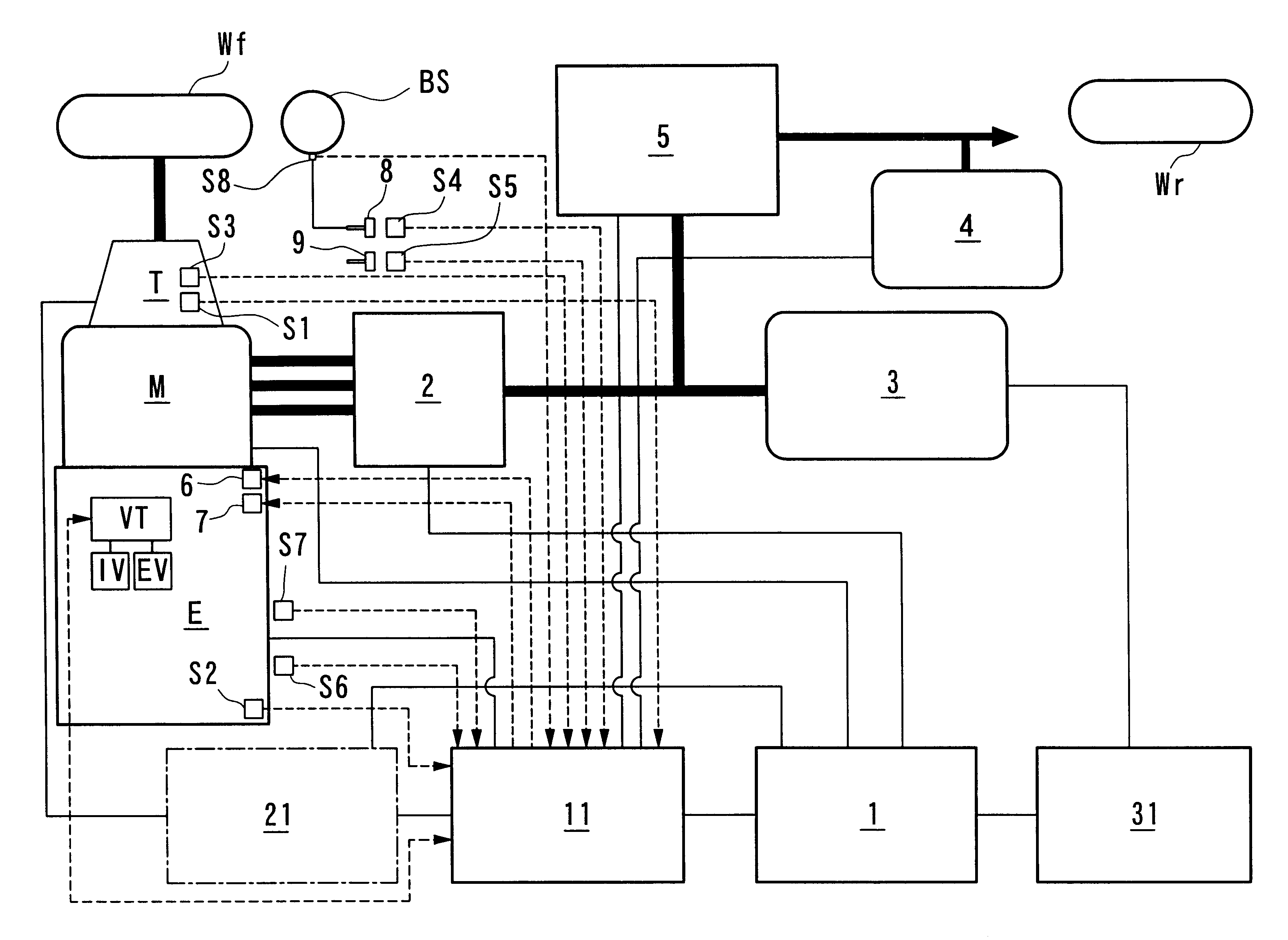
[0038]FIG. 1 shows a parallel hybrid vehicle according to the embodiment of the present invention, and is structured such that the engine E, the electric motor M, and the transmission T are coupled in series. The driving force of both the engine E and the electric motor M is transmitted to the front drive wheels Wf and Wf via a transmission comprising either an automatic transmission or a manual transmission. In addition, during deceleration of the hybrid vehicle, when drive force is transmitted from the front wheel Wf and Wf side to the electric motor M side, the electric motor M functions as a generator and generates what is called regenerative braking force, and the kinetic energy of the vehicle body is recovered as electrical energy. Here, Wr denotes the rear wheels.

[0039]The drive of the electric motor M and the regenerative actions are carried out by a power drive unit 2 that receive...


PUM


Abstract

A control apparatus for a hybrid vehicle for generating an appropriate amount of regeneration energy during deceleration. A control apparatus for a hybrid vehicle including an engine and electric motor for driving the hybrid vehicle wherein the engine comprises cylinders capable of deactivated operations and the motor executes regenerative braking when the vehicle is decelerating. The control apparatus of the present invention includes a cylinder deactivation determination device for determining whether or not the vehicle speed is appropriate for executing the cylinder deactivated operation, a regeneration amount calculating device for detecting whether the vehicle state is appropriate for regeneration and calculates the amount of regeneration; and further includes a compensation amount calculating device that compensates the amount of regeneration based on an all cylinder deactivated operation and the engine rotation speed.

Description

BACKGROUND OF THE INVENTION[0001]1. Field of the Invention[0002]The present invention relates to a control system for a hybrid vehicle, and in particular, to a control system for a cylinder deactivating type hybrid vehicle that can guarantee an appropriate amount of regeneration during deceleration.[0003]2. Description of the Related Art[0004]Conventionally, hybrid vehicles which carry motors as power sources for driving the vehicles in addition to the engine are known. There are two types of hybrid vehicles, and one of which is parallel hybrid vehicles in which the output of the engine is assisted by an electric motor.[0005]This parallel hybrid vehicle assists the output of the engine by an electric motor during acceleration, and various controls such as carrying out the charging of the battery and the like by regenerative breaking during deceleration are executed, and while guaranteeing the remaining charge (electrical energy) of the battery, the demands of the driver can be satis...

Claims


Application Information

Patent Timeline
Patent Type & Authority Patents(United States)
IPC IPC(8): B60K6/04B60K6/00F02D41/12F02D17/00F02D17/02F01L13/00F02D41/32F02D41/36B60K6/20B60K6/24B60W10/04B60K6/48B60K6/485B60K6/543B60K6/547B60L7/18B60L50/15B60L50/16B60W10/00B60W10/06B60W10/08B60W10/10B60W10/105B60W10/11B60W10/18B60W20/00F02D29/02
CPCB60K6/48B60W10/06B60W10/10F01L13/0005F01L13/0036F02D17/02F02D41/0087F02D41/123Y10T477/68B60W20/00B60W2510/0638B60W2510/0671B60W2520/10B60W2710/0644F02D2041/0012Y02T10/6221Y02T10/48B60L2240/441Y02T10/40Y02T10/62B60L7/18B60W10/24B60W10/04B60W20/40B60W2710/0633B60W2510/18
Inventor WAKASHIRO, TERUOMATSUBARA, ATSUSHIKITAJIMA, SHINICHITAKAHASHI, HIDEYUKINAKAUNE, KANSHINOHARA, TOSHINARI
Owner HONDA MOTOR CO LTD
Learn More