
Contact arrangement

a technology of contact arrangement and contact, applied in the direction of coupling contact member, coupling device connection, transportation and packaging, etc., can solve the problems of reducing the strength of a signal in a certain frequency band, transmission loss to increase in high-frequency signal transfer, and the above-described technology is not readily or easily applied to the contact arrangement for an antenna or a vehicle. , to achieve the effect of suppressing parasitic capacitan

Active Publication Date: 2005-08-23
KOJIMA PRESS IND CO LTD +1
View PDF12 Cites 22 Cited by
  • Summary
  • Abstract
  • Description
  • Claims
  • Application Information

AI Technical Summary

Benefits of technology

[0008]In view of the aforesaid problems, the present invention provides a contact arrangement which advantageously increases transmission characteristics. A contact arrangement for a high-frequency circuit according to this invention comprises a main body, an elastic member made of a metallic conductor and installed inside the main body, a contact head made of a conductor and pressed against an object to be contacted by a force exerted from the elastic member, an insulator inserted between the elastic member and the contact head to break electric continuity between the elastic member and the contact head, and a wire connected to the contact head to constitute a part of an electric conduction path. In addition to establishing electric conduction between the contact arrangement and the object to be contacted by the wire and the contact head rather than the elastic member, the elastic member is insulated from the contact head and placed apart from the contact head to suppress parasitic capacitance existing between the elastic member and the contact head.
[0010]In still another aspect of the present invention, a contact arrangement used for an antenna for a vehicle window comprises a main body, an elastic member made of a metallic conductor and installed inside the main body, a contact head made of a conductor and pressed against an contacting area of an antenna element attached to the vehicle window by a force exerted from the elastic member, an insulator inserted between the elastic member and the contact head to break electric continuity between the elastic member and the contact head, and a wire connected to the contact head to constitute a part of the electric conduction path. In addition to establishing electrical continuity with the contacting area of the antenna element by the wire and the contact head rather than the elastic member, the elastic member is insulated from the contact head and placed apart from the contact head, to thereby suppress parasitic capacitance existing between the elastic member and the contact head.

Problems solved by technology

For the reasons described, the above-described technology is not readily or easily applied to a contact arrangement for an antenna or for a vehicle.
Further, in the prior-art contact arrangement such as described above, a coil spring is typically used as a part of the electric conduction path, but this leads to problematic situations in which, for example, the inductance of the coil spring causes transmission loss to increase in high-frequency signal transfer.
One problem which often arises when the spring is placed in such a manner is that the strength of a signal decreases in a certain frequency band due to a parasitic capacitance existing between the spring and the ground electrode.

Method used


Image

  • Contact arrangement
  • Contact arrangement
  • Contact arrangement

Examples


Embodiment Construction

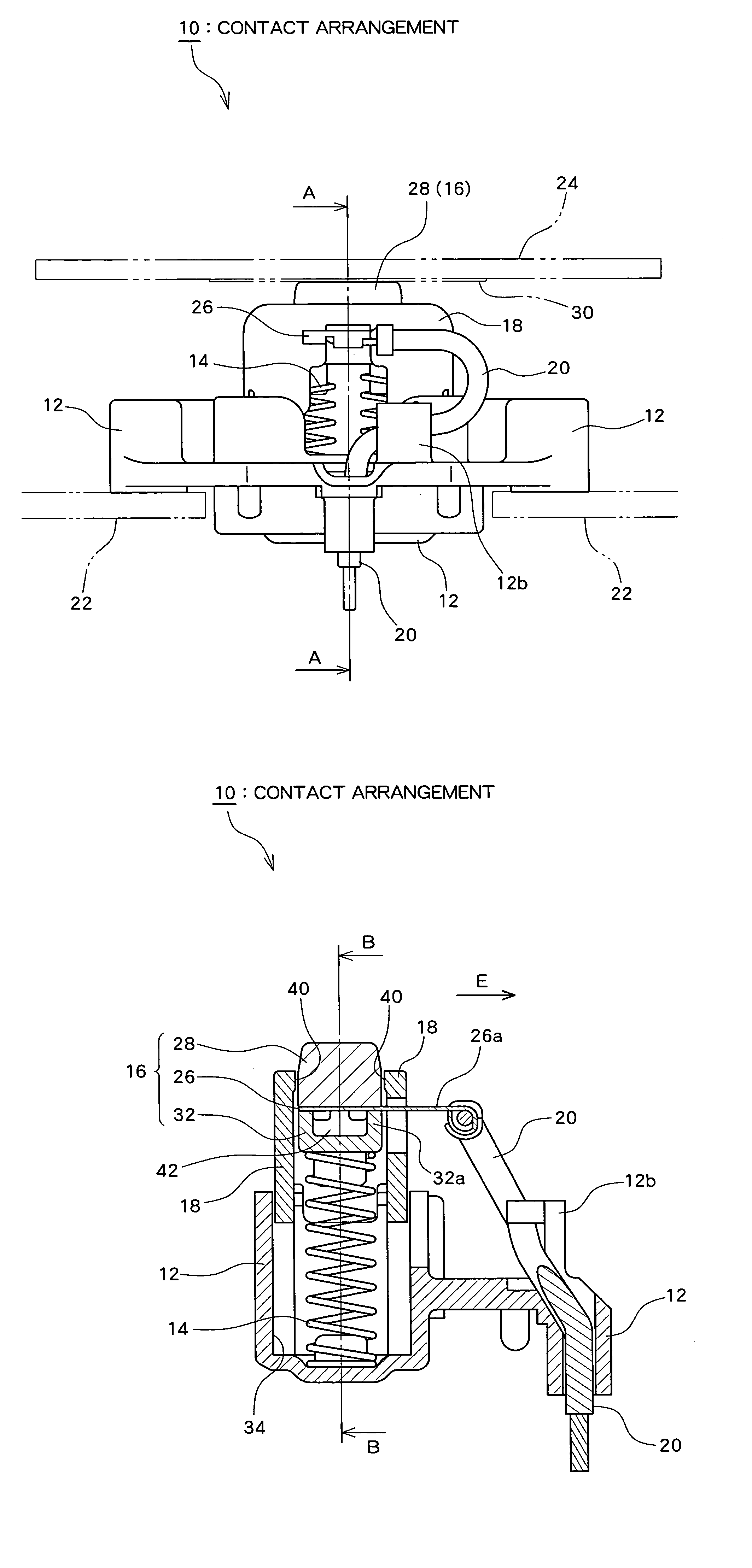
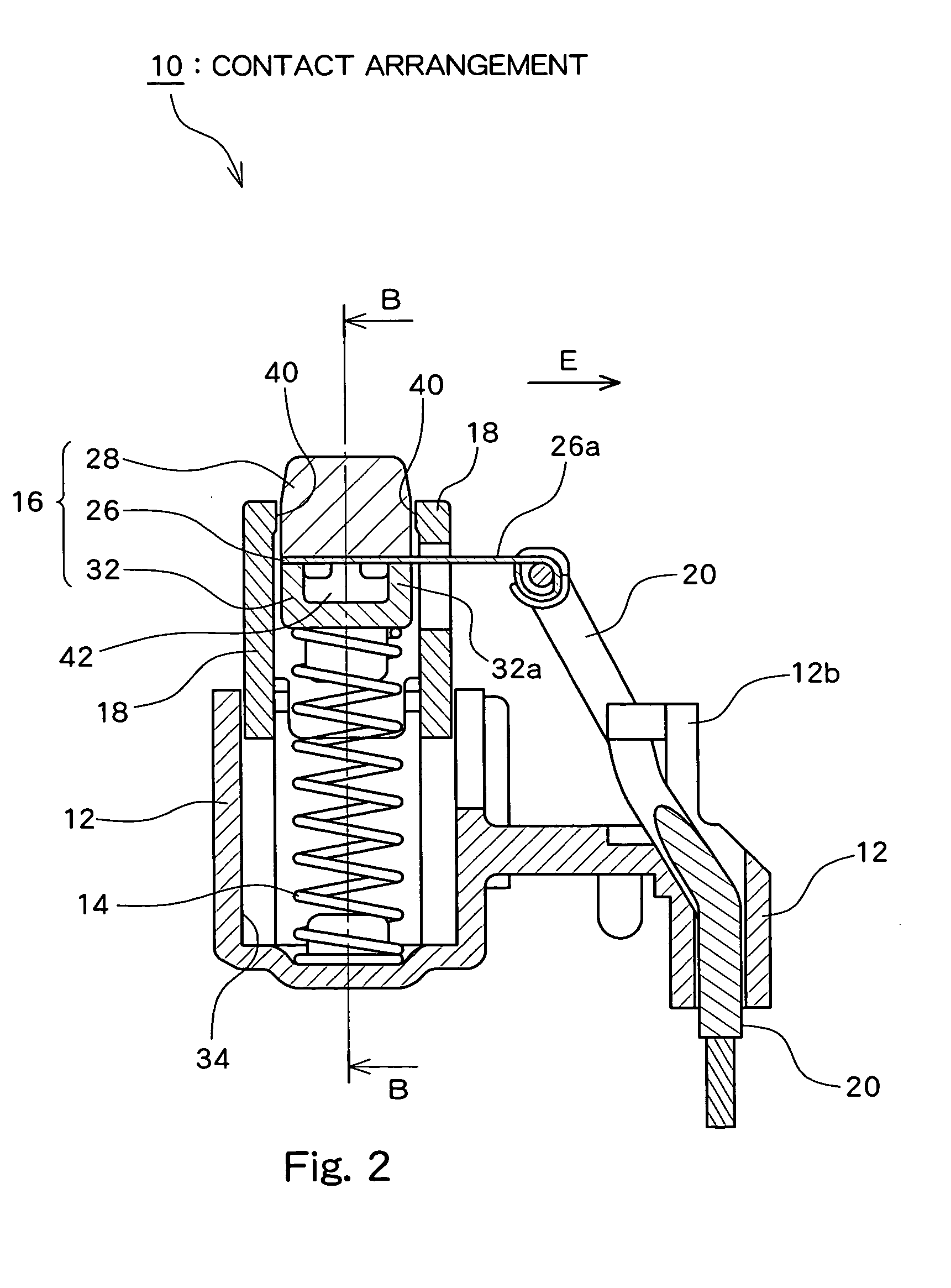
[0021]Referring to drawings, a preferred embodiment of this invention will be described below. FIG. 1 is an external view showing an example of a contact arrangement 10 according to this embodiment, FIG. 2 is a sectional view taken along the line A—A of FIG. 1, and FIG. 3 is a sectional view taken along the line B—B of FIG. 2.

[0022]The contact arrangement 10 includes a main body 12, an elastic member 14, a contact unit 16, an intermediate 18, and a wire 20. The contact arrangement 10 is used for forming an electrical conduction path between a first component 22 (such as, for example, a signal processor in an antenna for a vehicle window) and a second component 24 (such as, for example, a vehicle window) as an object to be contacted. In the example shown in FIGS. 1 to 3, the electrical conduction path is formed by electrically connecting a conductor pattern (not illustrated) of the first component 22, the wire 20, a metallic lead 26, an contact head 28, and a conductor pattern 30 of ...


PUM


Abstract

An elastic member made of a metallic conductor is installed inside a main body. A contact head made of a conductor is pressed by a force exerted from the elastic member against an object to be contacted. The contact head is connected to a wire constituting a part of an electric conduction path. An insulator for breaking electric continuity between the elastic member and the contact head is inserted between the elastic member and the contact head. In addition to establishing electrical continuity with the object to be contacted using the wire and the contact head rather than the elastic member, the elastic member is insulated from the contact head and placed apart from the contact head to suppress parasitic capacitance between the elastic member and the contact head.

Description

[0001]The disclosure of Japanese Patent Application No. 2003-400475 including specification, claims, drawings and abstract is incorporated herein by reference in its entirety.BACKGROUND OF THE INVENTION[0002]1. Field of the Invention[0003]The present invention relates to a contact arrangement configured such that an elastic member presses a contact member against an object to be contacted.[0004]2. Description of the Related Art[0005]FIG. 9 shows a conventional probe connector 70 which is used in a connecting area when electrical connection between print substrates is desired. The probe connector 70 shown in FIG. 9 comprises a stationary part 74 fixed onto a component 72 constituting one side of contact, a movable contactor 76 made of a conductor and movably housed in the stationary part 74, and a spring 78 made of a conductor and movably housed in the stationary part 74. The movable contactor 76 is brought into contact with a contact point of a component 80 constituting the other si...

Claims


Application Information

Patent Timeline
Patent Type & Authority Patents(United States)
IPC IPC(8): B60J1/00B60R16/02H01R12/00H01R13/24H01R13/22H01R4/00
CPCH01Q1/1271H01R13/2421H01R2201/02H01R2201/26H01R13/6471H01R13/6477
Inventor ISHIGURO, YOZONOMURA, TAKEHIROIWANAGA, SHINYATANAKA, HIDEAKIMAENO, SEIGENKUSHIMA, NAOKI
Owner KOJIMA PRESS IND CO LTD
Learn More