
Bicycle frame with rear passive suspension

a technology of passive suspension and bicycle frame, which is applied in the direction of friction roller based transmission, steering device, cycle equipment, etc., can solve the problems of reducing power transmission, adding too much weight, and limiting the flexibility of curved seat stays, so as to preserve or improve handling, maintain or improve rigidity, and isolate the rider

Inactive Publication Date: 2005-08-23
PEREZ RICARDO
View PDF20 Cites 31 Cited by
  • Summary
  • Abstract
  • Description
  • Claims
  • Application Information

AI Technical Summary

Benefits of technology

[0016]It is therefore an object of the present invention to provide a bicycle frame having a rear passive suspension system that effectively isolates the rider's saddle and pedals from lowamplitude to moderate-amplitude high-frequency vibration.
[0017]It is another object of this invention to provide a bicycle frame having a rear passive suspension system that significantly reduces maximum forces transmitted to the rider when striking objects or potholes.
[0018]Another object of this invention is to provide a bicycle frame having an integral rear passive suspension system that is laterally stiff for improved power transmission.

Problems solved by technology

Active suspensions, although common on off-road mountain bicycles, typically add too much weight and reduce power transmission under hard pedaling for high-performance road bicycles and other applications where weight, simplicity, and pedaling efficiency are critical.
However, the amount of flexibility in curved seat stays is typically quite limited (almost insignificant by comparison to the compressive flexibility of pneumatic rear tires) because of high material stresses, the possibility of bucking slender members under compression, and also because the right and left seat stays can flex at different rates depending on direction of wheel load.
This transverse load at the rear tire would flex the rear curved seat stays at different rates throwing the rear wheel out of alignment with the bicycle's frame; which would make a bicycle inefficient and hard to control when pedaling out of the saddle while climbing or sprinting.
Some recently developed bicycle frame designs use carbon fiber seat stays in place of metal to soften the ride, but are too stiff in compression to adequately flex to isolate the rider from vibration other than those of very low amplitude.
These designs are effective in isolating the saddle, but do not isolate the bottom bracket and hence the pedals, thus allowing much of the road vibration to reach the rider's legs.
Additionally, these frames are typically heavier because they must resist the high bending forces created by cantilevering much of the rider's weight from near the head tube of the frame.
Another disadvantage of this design is that the cantilever suspension system depends on varying the distance between the saddle and the bottom bracket, thus the pedaling forces promote rider bounce, which is inefficient.
The placement of stiffeners at these selected locations results in overall frame stiffness characteristics not previously considered achievable without substantial increase in the weight of the frame.
The telescoping portion supports the elastomer while allowing reciprocating movement along a major axis, but not allowing any rotational movement around that same axis.

Method used


Image

  • Bicycle frame with rear passive suspension
  • Bicycle frame with rear passive suspension
  • Bicycle frame with rear passive suspension

Examples


Embodiment Construction

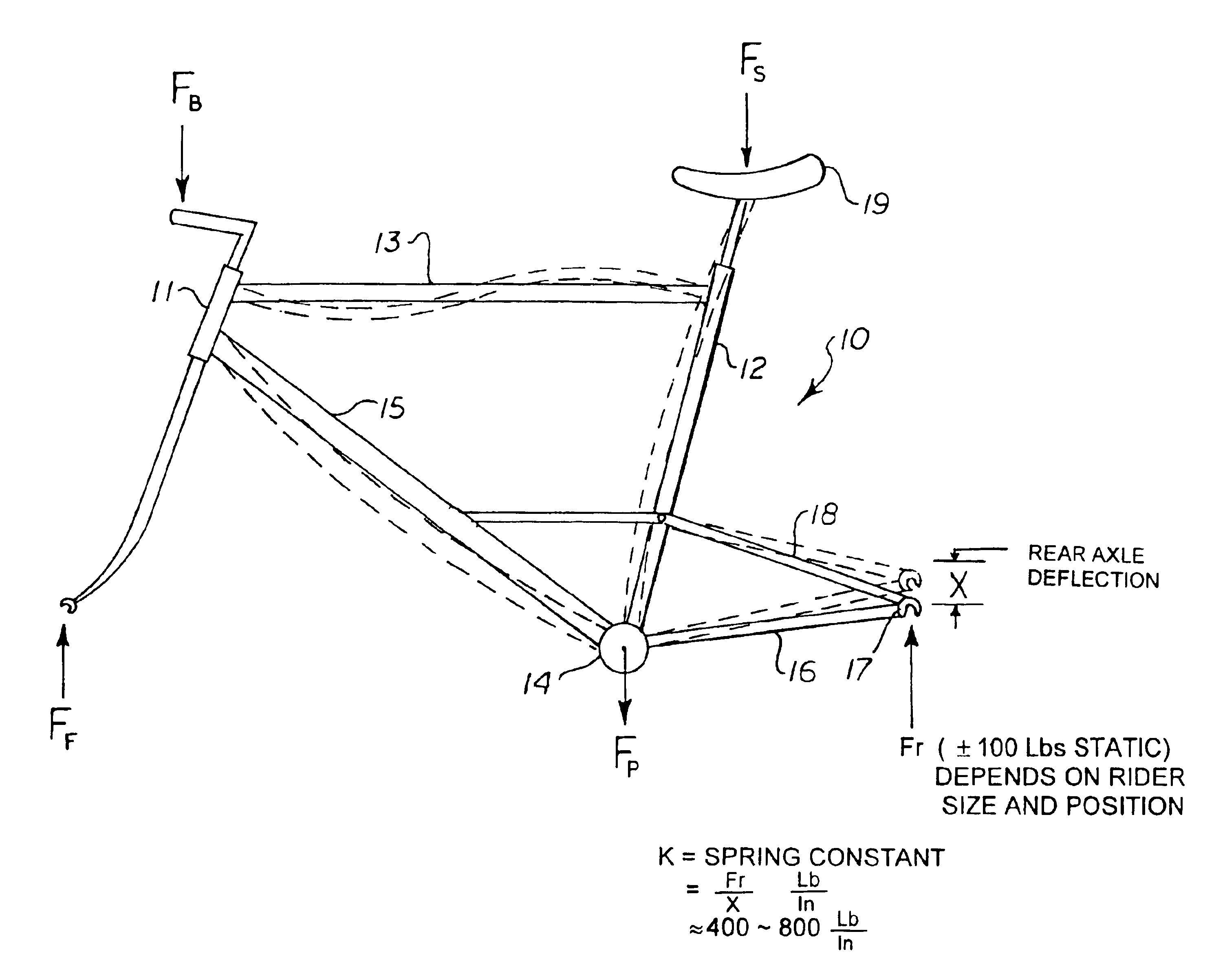
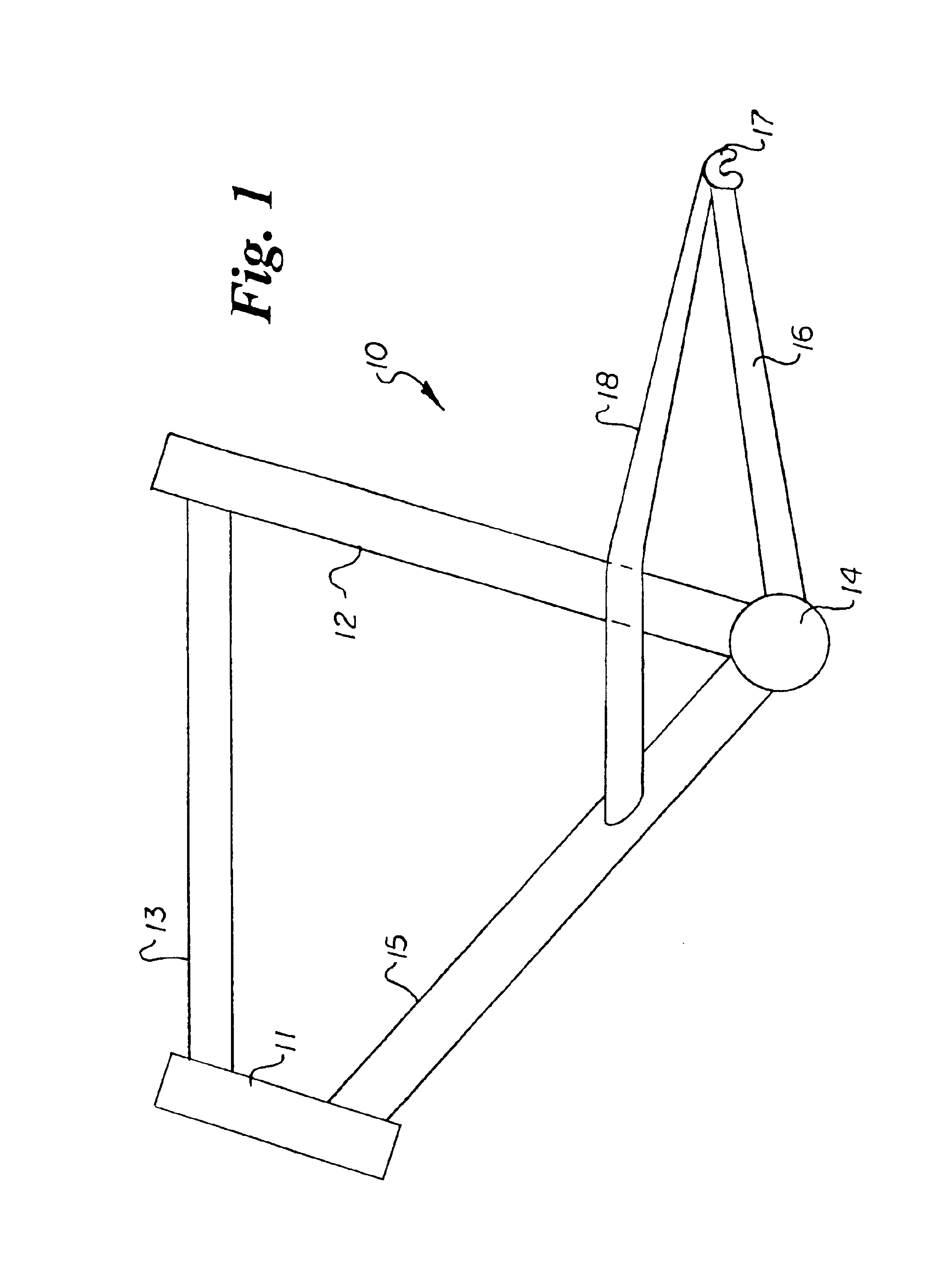
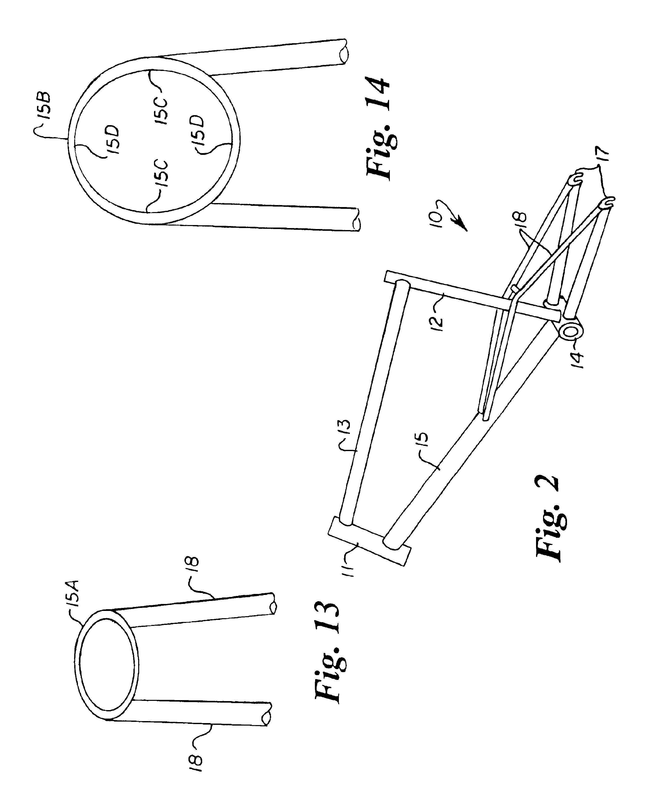
[0037]Referring to the drawings by numerals of reference, there is shown in FIGS. 1-3, a preferred bicycle frame 10 having a rear passive suspension system in accordance with the present invention. The present frame 10 has a head tube 11, a seat tube 12, a top tube 13 extending therebetween, a bottom bracket shell 14 at the bottom end of the seat tube, a down tube 15 extending angularly between the head tube and the bottom bracket shell, a pair of laterally spaced lower chain stay members 16 extending rearwardly from the bottom bracket shell, and a pair of laterally opposed rear wheel dropout brackets 17, one at the rear end of each lower chain stay member.

[0038]The present bicycle frame 10 eliminates the seat stays of a conventional road (or similarly designed cyclocross, hardtail mountain, hybrid, or city) bicycle frame and adds a second set of laterally spaced chain stays 18 (hereinafter referred to as upper chain stays 18) that connect the rear wheel with the bottom portions of ...


PUM


Abstract

A bicycle frame (10) having a rear passive suspension system configured to elastically deflect predominantly in a vertical direction under normal cycling loads so as to better isolate the rider from road-surface irregularities and roughness, while simultaneously maintaining or improving rigidity in other directions so as to preserve or improve handling. The frame (10) has a pair of upper chain stays (18) that control the rear wheel motion rigidly in five of the six degrees of freedom with stiffness comparable to existing road, cyclocross, hybrid, city, or hardtail mountain bicycle designs, while simultaneously allowing deflection of the tubular members and a significant amount of vertical movement of the rear wheel for ride compliance in order to improve comfort, handling, and safety.

Description

CROSS REFERENCE TO RELATED APPLICATION[0001]This application claims priority of U.S. Provisional Application Ser. No. 60 / 447,439 filed Feb. 14, 2003.BACKGROUND OF THE INVENTION[0002]1. Field of the Invention[0003]This invention relates generally to bicycle frame rear suspension systems, and more particularly to a bicycle frame with rear passive suspension configured to elastically deflect predominantly in a vertical direction under normal cycling loads so as to better isolate the rider from road-surface irregularities and roughness, while simultaneously maintaining or improving rigidity in other directions so as to preserve or improve handling.[0004]2. Brief Description of the Prior Art[0005]Many prior art bicycle frames with active suspension designs (those which use dedicated and purpose-built devices for flexibility and / or vibration control) often incorporate a spring to soften the ride. Active suspensions, although common on off-road mountain bicycles, typically add too much wei...

Claims


Application Information

Patent Timeline
Patent Type & Authority Patents(United States)
IPC IPC(8): B62K25/04B62K19/04B62K25/28
CPCB62K19/04B62K25/04B62K25/28B62K2025/041
Inventor PEREZ, RICARDO
Owner PEREZ RICARDO
Learn More