Rail producing method and producing equipment

a technology of rails and producing methods, applied in the direction of heat treatment equipment, measuring devices, furniture, etc., can solve the problems of difficult to achieve the required dimensional accuracy at a portion within, rarely used technology in actual production, and difficult to achieve the required dimensional accuracy. , to achieve the effect of improving productivity and yield

Inactive Publication Date: 2005-08-23
NIPPON STEEL CORP
View PDF33 Cites 3 Cited by
  • Summary
  • Abstract
  • Description
  • Claims
  • Application Information

AI Technical Summary

Benefits of technology

[0008]The present invention is accomplished to solve the problems of the above-mentioned prior arts, and provides a method and equipment for producing a rail, the method an

Problems solved by technology

Furthermore, though the technologies of producing an ultra-long rail 500 feet or more in length at a stroke from a continuous casting process to a final process have been disclosed recently in U.S. Pat. Nos. 5,018,666 and 5,419,387, those technologies are seldom put to practical use in actual production.
However, when a rail is produced through a continuous process, an en of the rail is a portion to which rolling or straightening can hardly be applied.
In a rolling process, it is difficult to achieve a required dimensional accuracy at a portion within the range from he tip or tail end of a rail to a position a certain length distant from either of them.
In addition, when a straightening treatment is required and thus a straightener wherein a plurality of rolls are arranged in a zigzag pattern is used, the range from

Method used


Image

  • Rail producing method and producing equipment
  • Rail producing method and producing equipment

Examples


example

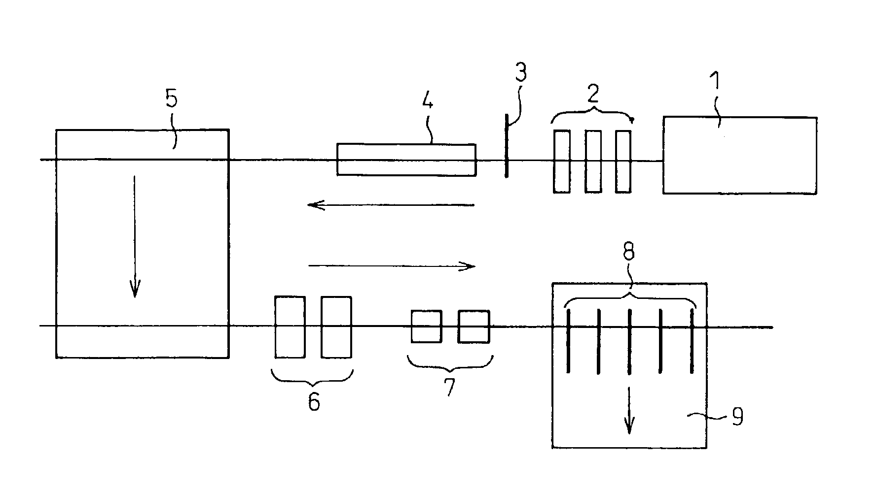
[0037]As an example of the present invention, six product rails 25 m in length each were produced through the processes of: subjecting a mother rail 153 m in length produced beforehand by heating, rolling and then removing non-rolled portions to an accelerated-cooling from a temperature in the austenite range or higher to about 500° C. at a cooling rate of 2° C. / sec.; successively naturally cooling the mother rail to an ordinary temperature; thereafter subjecting it to straightner and inspection apparatuses; and finally cutting and removing both the end portions in the length of 1.5 m each and, at the same time, cutting the other portion in the length of the products using seven units of cold-sawing machines.

[0038]In addition, as a comparative example, six product rails 25 m in length each were produced through the processes of: cutting a mother rail 153 m in length produced beforehand by heating, rolling and then removing non-rolled portions into six pieces of rails 25.5 m in lengt...


PUM

PropertyMeasurementUnit
Temperatureaaaaaaaaaa
Lengthaaaaaaaaaa

Abstract

The present invention provides a method and equipment for producing a rail, the method and equipment being capable of lowering a bend at an end of a rail effectively and the truncation amount thereof. The present invention is a method for producing a rail, characterized by: cooling a hot-rolled mother rail to an ordinary temperature substantially while the length thereof after the hot rolling is maintained; and thereafter cutting the mother rail simultaneously in a predetermined length with at least three cold-sawing machines. Further, the present invention is equipment for producing a rail, characterized by equipped with: a transfer bed capable of moving a mother rail cooled to an ordinary temperature substantially while the length thereof after hot rolling is maintained in the rolling direction and/or in the direction perpendicular to the rolling direction; and at least three cold-sawing machines disposed in parallel with each other on said transfer bed.

Description

CROSS-REFERENCE TO RELATED APPLICATIONS[0001]This application is a national stage application of PCT Application No. PCT / JP02 / 05308 which was filed on May 30, 2002 (the “International Application”). This application claims priority from the International Application pursuant to 35 U.S.C. § 365. The present application also claims priority under 35 U.S.C. § 119 from Japanese Patent Application No. 2001-161676 which was filed on May 30,2001. The entire disclosures of these applications are incorporated herein by reference.TECHNICAL FIELD[0002]The present invention relates to a method and equipment for producing a rail and, in particular, to a method and equipment capable of producing a rail with great efficiency and suppressing the generation of a bend at an end of the rail.BACKGROUND ART[0003]A generally employed method for producing a rail includes the processes of: heating a bloom and hot-rolling it into a predetermined shape; then cutting the hot-rolled material in lengths close t...

Claims


Application Information

Patent Timeline
IPC IPC(8): B23D45/10B23D45/00B21B43/00B21B45/02B21B38/00B21B1/08B21B15/00
CPCB21B15/0007B21B43/00B23D45/003B23D45/10B21B1/085B21B38/00B21B2015/0014Y10T29/49991B21B2045/0212Y10T29/5184Y10T29/49989B21B2015/0071Y10T83/659Y10T83/6588
Inventor ONODERA, NORIAKISHIBATA, MASAFUMIMIWA, MASANORIFUJITA, KAZUO
Owner NIPPON STEEL CORP
Why Eureka
Try Eureka