
Semiconductor wafer thinning method, and thin semiconductor wafer

a technology of semiconductor wafers and thinning methods, which is applied in the direction of grinding machines, grinding machine components, manufacturing tools, etc., can solve the problems of high yield, difficult to use the protective tape for large-scale production, and high breakage of the wafer during the processing step or upon peeling of the protective tape, etc., and achieve the effect of low cos

Inactive Publication Date: 2005-08-16
SHIN-ETSU HANDOTAI CO LTD
View PDF12 Cites 28 Cited by
  • Summary
  • Abstract
  • Description
  • Claims
  • Application Information

AI Technical Summary

Benefits of technology

[0008]The present invention was accomplished in view of the aforementioned problems, and its object is to provide a method for thinning a semiconductor wafer, which enables production of semiconductor wafers having a thickness of about 120 μm or less without generating breakage such as cracking or chipping during the processing step and so forth as much as possible at a low cost, and a semiconductor wafer, in particular, one produced in a large scale production to have a diameter of 6 inches or more, made further thinner compared with conventional products.

Problems solved by technology

If it is attempted to thin wafers further thinner by using the aforementioned conventional technique, the probability of breakage of the wafer during the processing step or upon peeling of the protective tape becomes high, and therefore it is extremely difficult to use it for large scale production.
Therefore, yield is degraded and cost is increased.
As a result, it cannot meet large scale production.
That is, if it is attempted to obtain a thickness of 120 μm or less by the conventional technique, it is substantially impossible to prevent cracking unless a wafer having a diameter of 4 inches (100 mm) or less is used.

Method used


Image

  • Semiconductor wafer thinning method, and thin semiconductor wafer
  • Semiconductor wafer thinning method, and thin semiconductor wafer
  • Semiconductor wafer thinning method, and thin semiconductor wafer

Examples


examples

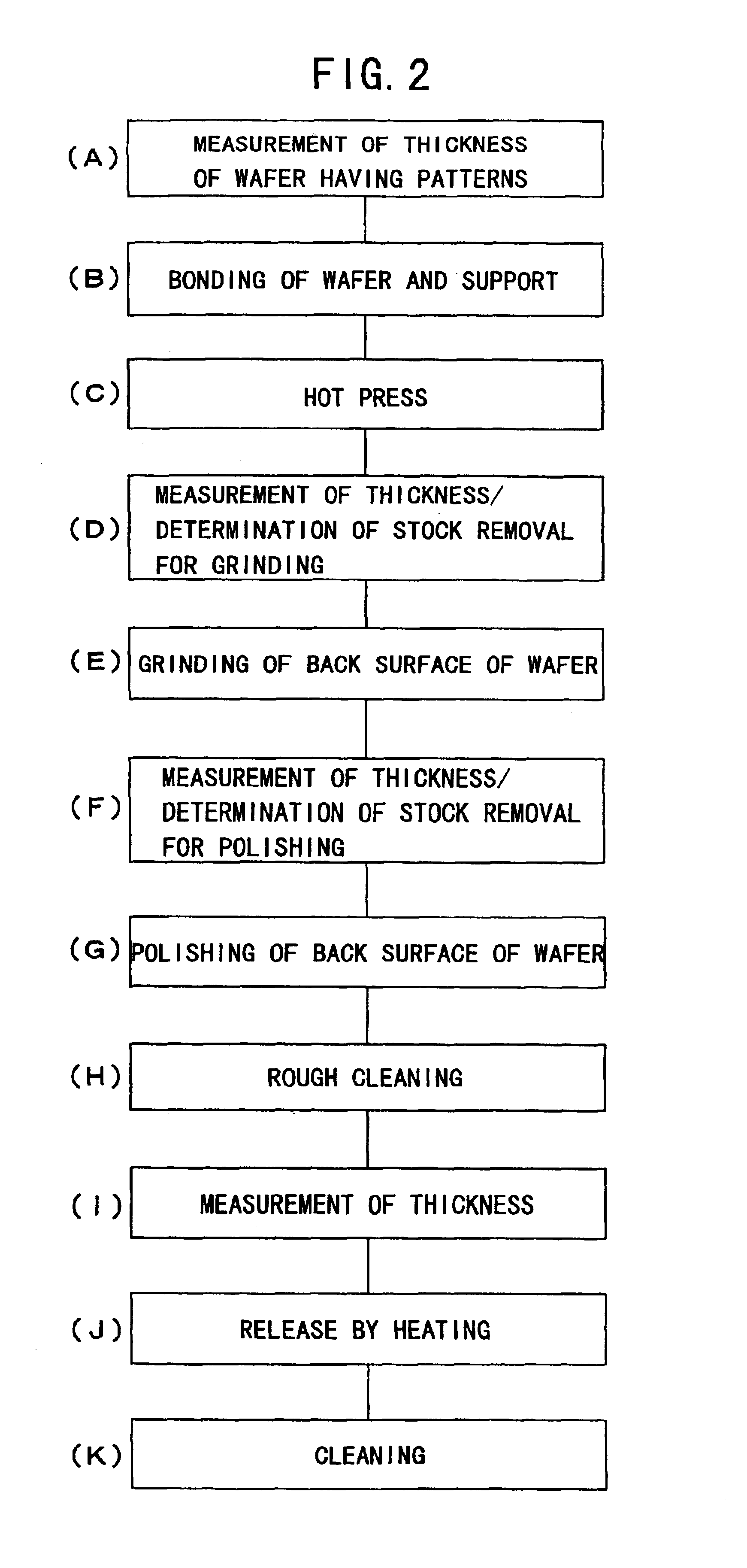
[0044]A surface of a 6-inch (150 mm) silicon wafer in which semiconductor devices are formed on its surface (wafer having patterns) was adhered to a surface of a silicon wafer via a thermal release double-sided adhesive sheet to form a bonded composite. Then, the back surface of the wafer having patterns was subjected to surface grinding by using a surface grinding machine so that the wafer should have a thickness of 105±15 μm. Subsequently, the wafer was released by heating and its thickness was measured. The thickness of the wafer before the grinding and the thickness of the wafer thinned by the grinding are shown in Table 1. As for the grinding conditions, a grinding stone of #2000 STD was used, and grinding stone rotation number: 5000 rpm and grinding stone feeding speed: 0.4 μm / min were used. As the thermal release double-sided adhesive sheet, REVALPHA produced by NITTO DENKO CORP. (thickness of base material: 50 μm, thermal release temperature: 120° C.) was used.

[0045]

TABLE 1T...


PUM


Abstract

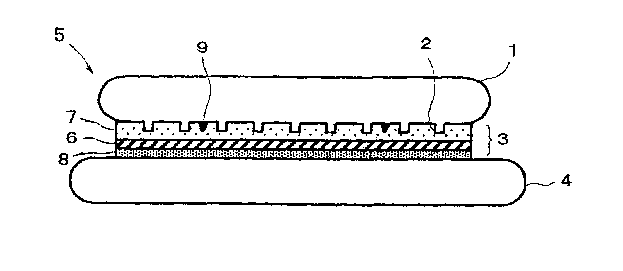
In a method for thinning a semiconductor wafer by grinding a back surface of the semiconductor wafer in which semiconductor devices 2 are formed on its surface, the surface of the semiconductor wafer 1 is adhered to a support 4 via an adhesive layer 3, the back surface of the semiconductor wafer is ground while holding the support, and then the thinned semiconductor wafer is released from the support. Preferably, a semiconductor wafer is used as the support, a thermal release double-sided adhesive sheet is used as the adhesive layer, and they are separated by heating after grinding. Thus, there are provided a method for thinning a semiconductor wafer, which enables production of semiconductor wafers having a thickness of about 120 μm or less without generating breakage such as cracking or chipping during the processing step and so forth as much as possible at a low cost, and a semiconductor wafer thinned further compared with conventional products in spite of a large diameter of 6 inches (150 mm) or more.

Description

TECHNICAL FIELD[0001]The present invention relates to a method for thinning a semiconductor wafer, which is a method for making a semiconductor wafer into a thin semiconductor wafer suitable for producing, for example, semiconductor devices such as IC cards, solar cells and thin film transistors or semiconductor integrated circuits (IC) consisting of multiple semiconductor devices.BACKGROUND ART[0002]In the production of semiconductor devices such as IC cards, solar cells and thin film transistors or semiconductor integrated circuits, miniaturization of devices or degree of freedom concerning use thereof can be improved by making thickness of semiconductor wafers used as substrates therefor sufficiently thinner.[0003]In particular, for IC cards and so forth, necessity for thinning semiconductor wafer is high, and it is desired that chips constituting circuits should be made thinner as much as possible.[0004]In a conventional technique, in order to produce such a thin semiconductor w...

Claims


Application Information

Patent Timeline
Patent Type & Authority Patents(United States)
IPC IPC(8): H01L21/02H01L21/304B24B7/22B24B37/30H01L21/687
CPCB24B7/228B24B41/068B24B49/00H01L21/304H01L21/6835Y10S438/928Y10S438/977Y10S438/959H01L2221/68318H01L2221/68327H01L2221/6834H01L2221/68381
Inventor OKADA, MAMORUNAKAJIMA, YUKIO
Owner SHIN-ETSU HANDOTAI CO LTD
Learn More