
Infusion clamp

a technology of infusion device and clamping device, which is applied in the direction of surgical forceps, catheters, snap fasteners, etc., can solve the problems of cumbersome and time-consuming placement of tools and devices, and achieve the effect of quick and easy connection of infusion device and quick and easy insertion of infusion devi

Inactive Publication Date: 2005-08-16
BAYLOR COLLEGE OF MEDICINE
View PDF25 Cites 6 Cited by
  • Summary
  • Abstract
  • Description
  • Claims
  • Application Information

AI Technical Summary

Benefits of technology

The present invention relates to an infusion clamp and method for infusing a chambered body. The infusion clamp has a plurality of opened positions and a closed position, and includes a first clamping member, a second clamping member, a hinge member, and an infusion device support member. The infusion device support member is disposed above the first clamping member and the second clamping member, and the clamping members have a mating surface and a partial passageway that form a complete passageway when the infusion clamp is in the closed position. The infusion clamp can be placed on the outer wall of the chambered body and secured in place. The technical effects of the invention include improved infusion control, flexibility in infusion device placement, and ease of use.

Problems solved by technology

One problem with prior techniques and devices for infusing the right atrium with fluid is that the techniques and devices are cumbersome and take time to be put in place.

Method used


Image

  • Infusion clamp
  • Infusion clamp
  • Infusion clamp

Examples


Embodiment Construction

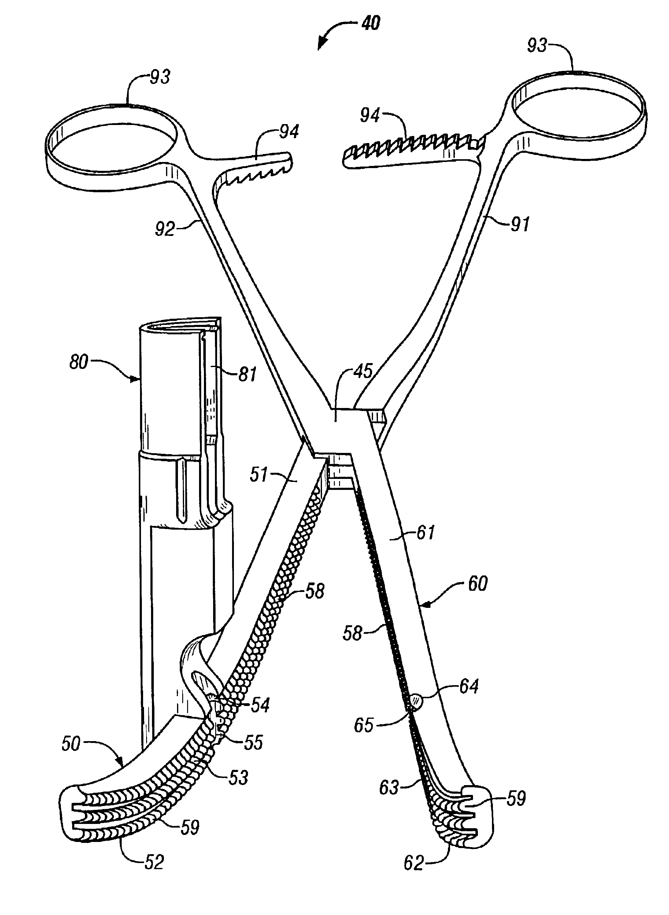
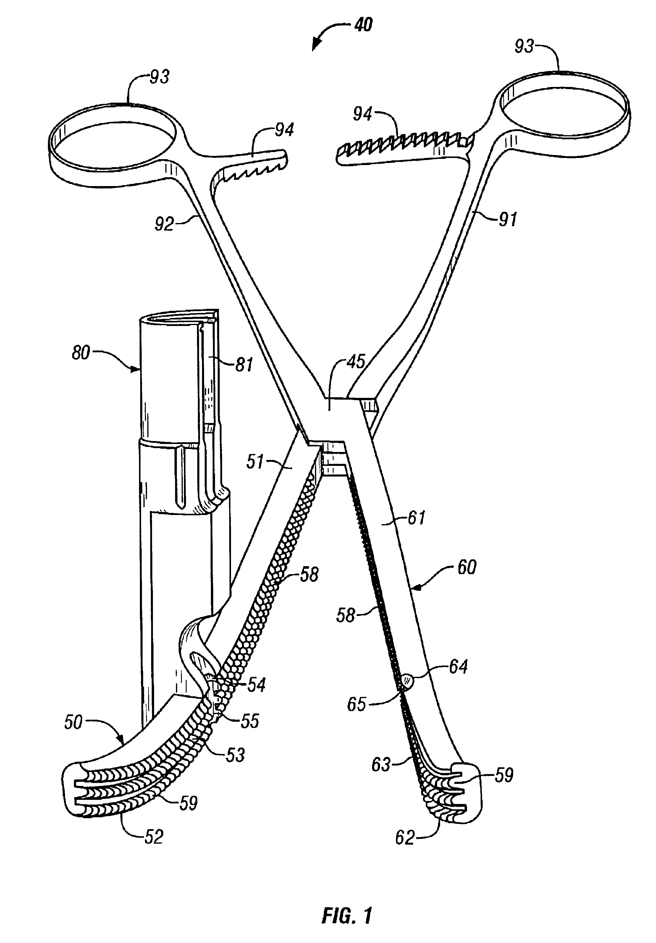
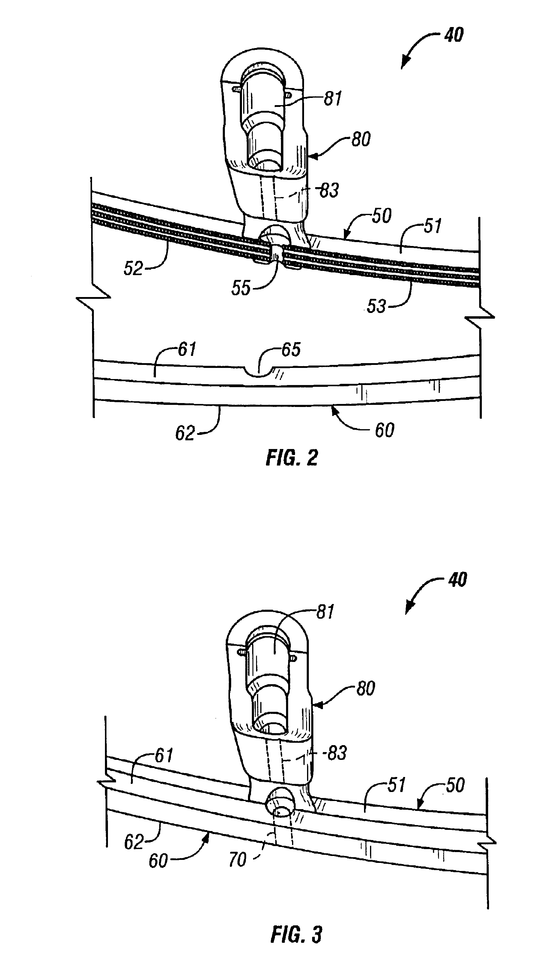
[0021]Broadly, the present invention is directed to improved infusion clamps and methods of infusing a chambered body with fluid. The infusion clamps provide a seal to the chambered body to permit large volumes of fluid to be transfused into the chambered body. As used herein, “chambered body” is defined as an organ, body cavity, artery, e.g., the aorta, vein, e.g., the vena cava, or other body part that includes at least one outer wall and at least one chamber or cavity which may require the infusion, or instillation, of a large volume of fluid. For example, during resuscitative thoracotomy, large volumes of fluid or blood are require to be infused into the right atrium of the heart. The infusion clamps of the present invention are useful in such a procedure because the infusion clamp can be easily secured to the appendage of the right atrium and a catheter can then be easily secured to the infusion clamp and inserted through the infusion clamp and through the outer wall of the rig...


PUM


Abstract

The present invention is directed to an infusion clamp including a first clamping member having a first side surface, a second side surface, a first mating surface, and an aperture disposed between the first side surface and the second side surface thereby forming a passageway there between; a second clamping member having a third side surface, a fourth side surface, and a second mating surface; a hinge member disposed along and in communication with first clamping member and second clamping member, thereby facilitating the movement of the infusion device from the closed position of the infusion clamp to the plurality of opened positions of the infusion clamp, and from the plurality of opened positions to the closed position; and an infusion device support member disposed above the passageway thereby permitting an infusion device to be disposed within the infusion device support member and through the passageway. The infusion clamp permits quick and easy attachment of an infusion device, e.g., a catheter, to a chambered body, e.g., the right atrium of the heart, for infusion of fluid into the chambered body such as during emergency surgery or triage on a patient. Methods of infusing chambered bodies are also disclosed.

Description

RELATED APPLICATION[0001]This application claims the benefit of U.S. Provisional patent application Ser. No. 60 / 378,582, filed May 7, 2002.BACKGROUND OF THE INVENTION[0002]1. Field of the Invention[0003]The present invention is directed to an infusion clamp, and in particular, an infusion clamp for securing an infusion device, e.g., a catheter, to the wall of a chambered body such as the right atrium of the heart for quick and easy infusion of fluid into the chambered body. The present invention is also directed to a method of infusing a chambered body with a fluid using the infusion clamps of the present invention.[0004]2. Description of Related Art[0005]During medical emergencies, physicians are sometimes required to infuse, or instill, a large amount of fluid into a patient's body, and more specifically, a chambered body such as the heart. In particular, after traumatic accidents in which a patient has lost a large amount of blood, an emergency room physician is required to acces...

Claims


Application Information

Patent Timeline
Patent Type & Authority Patents(United States)
IPC IPC(8): A61B17/28A61B17/34
CPCA61B17/282A61B2017/2808Y10T24/44A61B17/3417Y10S128/26A61B17/3415
Inventor SCOTT, BRADFORD G.WALL, MATTHEW J.
Owner BAYLOR COLLEGE OF MEDICINE
Learn More