
Throttle control for a small engine

a technology of throttle system and piston valve, which is applied in the direction of electric control, charge feed system, combustion air/fuel air treatment, etc., can solve the problems of high cost and complexity, low accuracy, and increase the complexity of the engine, so as to reduce the complexity and manufacturing cost of the internal combustion engin

Inactive Publication Date: 2005-08-16
DELPHI TECH INC
View PDF13 Cites 4 Cited by
  • Summary
  • Abstract
  • Description
  • Claims
  • Application Information

AI Technical Summary

Benefits of technology

The invention is an internal combustion engine with a unique design that simplifies the engine's construction and allows for variable engine speed control. It eliminates the need for a governor, rotary mechanical throttle, and cable or mechanical linkages. This makes it ideal for small engines used in powering portable electric generators, yard equipment, or outboard motors. The engine includes a combustion air inlet with a circular poppet valve seat and a valve pintle that can be adjusted to regulate the flow of air into the engine. The position of the pintle is controlled by an actuator that is responsive to engine speed sensors and an electronic controller. The controller adjusts the position of the pintle based on a programmed algorithm to achieve any desired engine speed, especially at fixed engine loads. Overall, the invention simplifies engine construction, reduces complexity, and allows for efficient engine speed control.

Problems solved by technology

Such systems typically are of low accuracy and add significant numbers of components, and thus cost and complexity, to an engine.
Such systems are also prone to failure from clogging or damage by environmental debris such as grass, stones, and wood chips.

Method used


Image

  • Throttle control for a small engine
  • Throttle control for a small engine
  • Throttle control for a small engine

Examples


Embodiment Construction

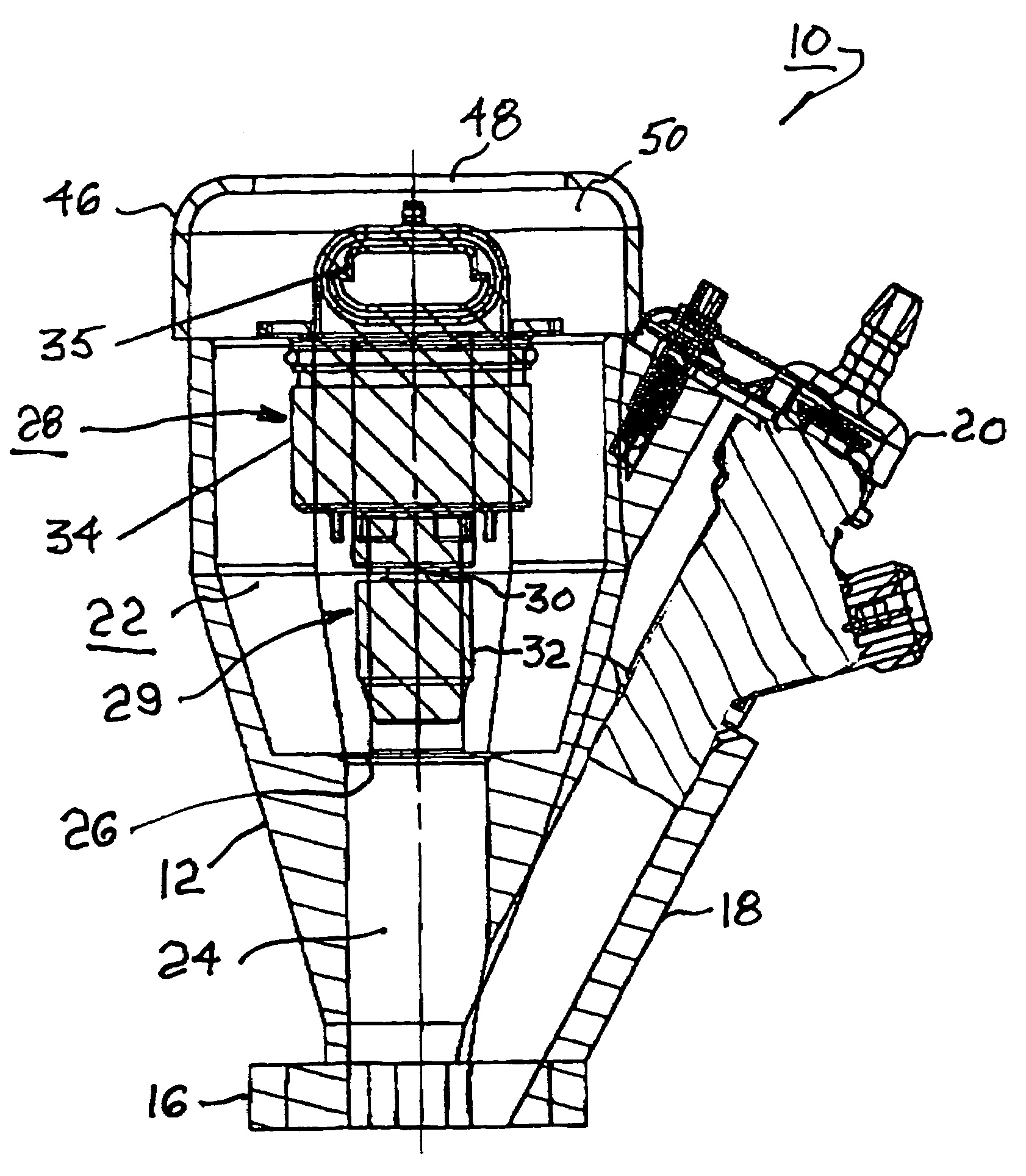
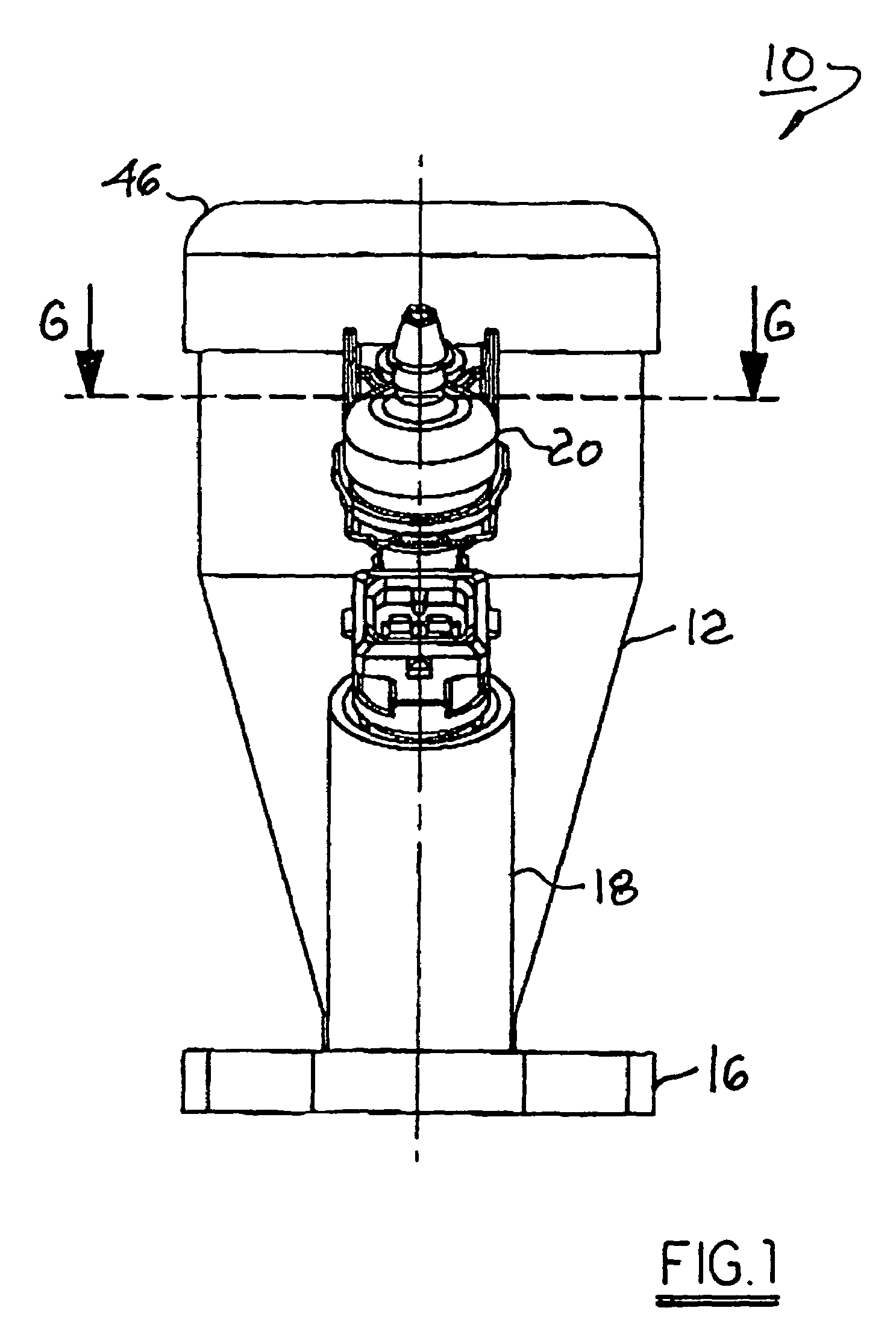
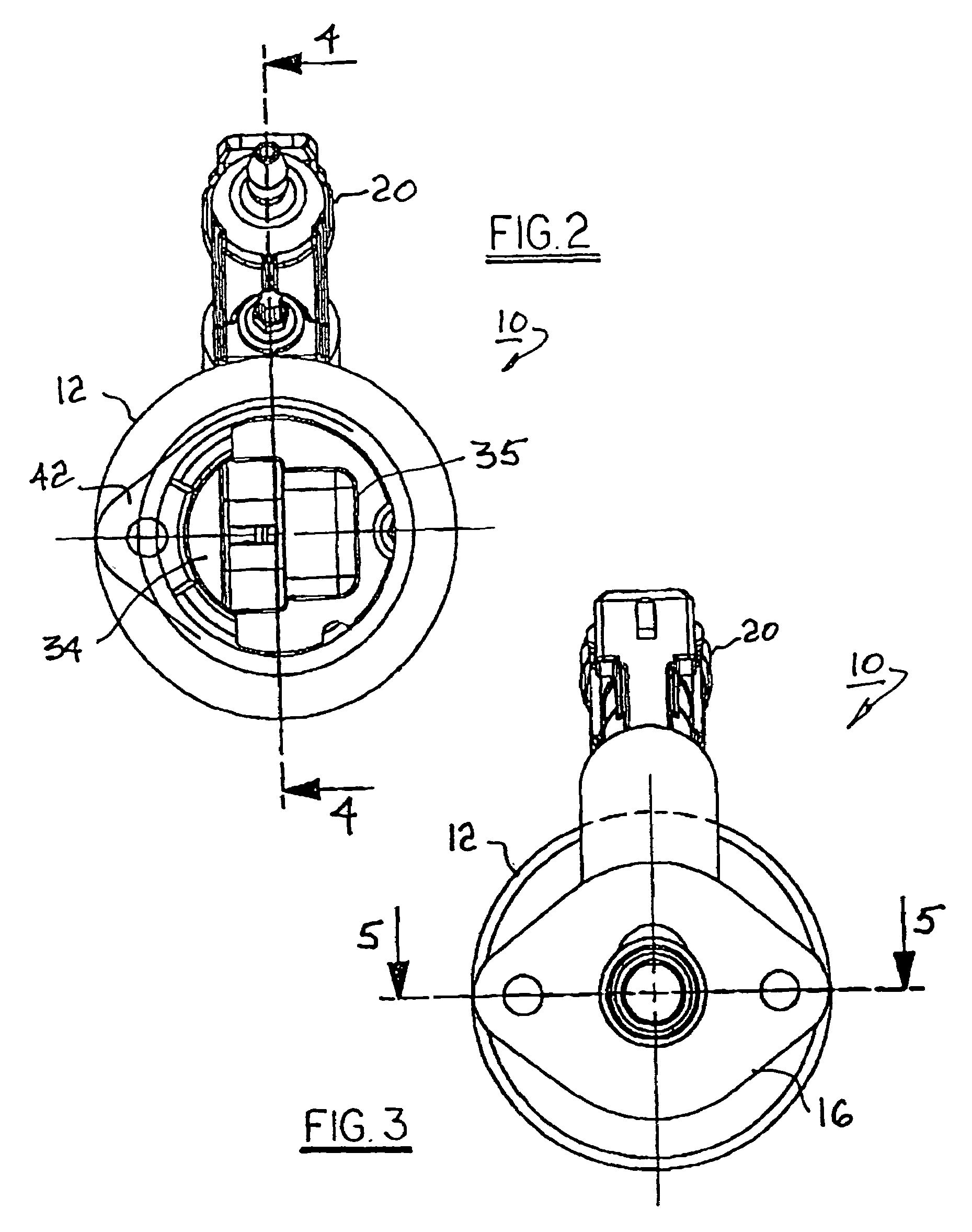
[0021]Referring to FIGS. 1 through 6, an engine speed control assembly 10 in accordance with the invention includes a valve housing 12 defining means for the entrance of combustion air into an internal combustion engine 14. Housing 12 is provided with a flange 16 for attachment conventionally to an intake port 13 of engine 14 (both shown schematically in FIG. 5) as by bolt holes 15. A sidearm 18 supports a conventional fuel injector 20 for providing fuel to intake port 13 in known fashion. Fuel injector 20 need not be considered further as a part of this disclosure.

[0022]Housing 12 encloses an outer chamber 22 and an inner chamber 24 separated by a valve seat 26 which is preferably circular. Inner chamber 24 defines a valve throat leading to intake port 13. Disposed in chamber 22 coaxially with seat 26 is a poppet valve assembly 28 including a pintle assembly 29 comprising a valve shaft 30 and connected valve head 32 for cooperating with seat 26 to vary the cross-sectional open area...


PUM


Abstract

A speed control apparatus for an internal combustion engine including a poppet valve seat and a poppet valve pintle assembly disposed coaxially for variably regulating the flow of air into the engine across the valve seat. The pintle is axially positioned by a stepper motor actuator responsive to an engine speed sensor and electronic controller. The controller varies the axial position of the pintle in accordance with a programmed algorithm to provide any desired engine speed, and especially a fixed engine speed, under a range of engine loads. The invention eliminates the need for a governor, rotary mechanical throttle, and cable or mechanical linkages, and is especially useful for small engine applications such as in powering a portable electric generator, yard equipment, or outboard motor.

Description

CROSS REFERENCE TO RELATED APPLICATION[0001]The present application is a continuation application of U.S. application Ser. No. 10 / 238,836 filed on Sep. 6, 2002.TECHNICAL FIELD[0002]The present invention relates to means for controlling the speed of an internal combustion engine; more particularly, to valve means for throttling the flow of combustion air into an internal combustion engine; and most particularly, to a poppet valve throttle system for controlling the speed of a small internal combustion engine, and especially a fixed speed.BACKGROUND OF THE INVENTION[0003]Prior art internal combustion engines typically employ a butterfly-type valve for throttling the volume of air admitted to the engine. Such a valve comprises a rotatable shaft mounted transversely of an engine manifold inlet and supporting a plate which may be rotated by the shaft to variably occlude the inlet.[0004]In many applications, especially non-automotive, an engine may be required to operate for long periods ...

Claims


Application Information

Patent Timeline
Patent Type & Authority Patents(United States)
IPC IPC(8): F02D9/12F02D9/08F02DF02M35/10
CPCF02D9/08F02D9/12F02M35/10216
Inventor GARRICK, ROBERT D.WITZEL, DONALD G.IANNONE, CHARLES A.
Owner DELPHI TECH INC
Learn More