
Water well monitoring system

Inactive Publication Date: 2005-08-16
EHNDRESS KHAUZER GMBKH KO KG
View PDF11 Cites 11 Cited by
  • Summary
  • Abstract
  • Description
  • Claims
  • Application Information

AI Technical Summary

Benefits of technology

[0010]The present invention provides an apparatus and method for monitoring a liquid level in a 4-20 mA closed loop system. An object is to provide an inexpensive, rugged hydrostatic sensing element which will fit down a small pipe or well casing, and provide the user with a display readout of the water level in the well. Hydrostatic sensing of well water level has existed before, but not packaged with battery operated power supply / display units, nor economically for the use by private well owners and at remote locations.
[0011]For privately owned wells in regions with limited resources, the practical, economical, easy-to-use water level monitoring system described here offers many beneficial and previously unavailable features to the user. It also offers benefits to society in general as information will promote water conservation, preserving needed water table resources. And finally, it will also provide government agencies with previously unavailable methods and devices for collection of regulatory and / or scientific information. Some of these benefits are:

Problems solved by technology

Hydrostatic sensing of well water level has existed before, but not packaged with battery operated power supply / display units, nor economically for the use by private well owners and at remote locations.

Method used


Image

  • Water well monitoring system
  • Water well monitoring system
  • Water well monitoring system

Examples


Embodiment Construction

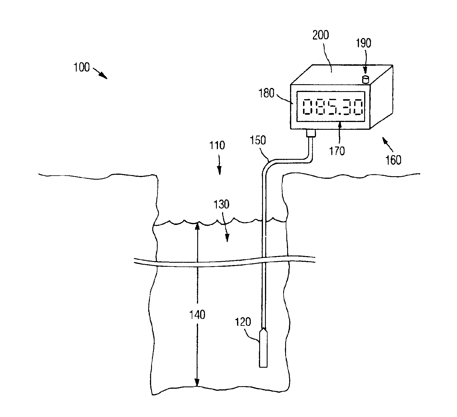
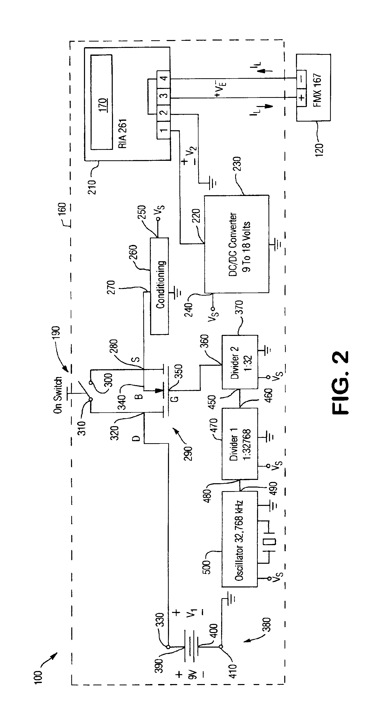
[0043]FIG. 1 is an illustration of an exemplary water well monitoring system 100 according to the present invention as installed in a typical operating environment such as, for example, a well 110. In general, a hydrostatic pressure sensor 120 measures a pressure exerted by a column of fluid (or “head pressure”) and generates a signal corresponding to the pressure. Depending on the density of the fluid, among other things, the pressure signal is used to determine the height 140 of the column (i.e., the fluid level). To this end, the system 100 includes a 4-20 mA loop-powered hydrostatic pressure sensor 120, which is a model No. FMX 167 sensor available from Endress+Hauser, Inc. of Greenwood, Ind. Accordingly, Endress+Hauser, Inc.'s application notes TI 351 P / 24 / ae / 04.01 © 2001 Endress+Hauser, Inc. for the FMX 167 are incorporated herein by reference. However, it is noted that other suitable hydrostatic pressure sensors may be used in alternative embodiments. Furthermore, it will be ...


PUM


Abstract

An apparatus and method for monitoring a liquid level in a 4-20 mA closed loop system are provided. A process instrument and a measuring unit are powered for a predetermined time and power is provided by a battery.

Description

FIELD OF THE INVENTION[0001]The present invention relates generally to the measurement of water levels in wells, and, more particularly, to a self-powered 4-20 mA loop hydrostatic pressure based well monitoring apparatus and method.BACKGROUND[0002]In many regions of the U.S. and other countries, water resources are limited and privately owned wells are located in places without access to electrical power. Water conservation and preservation of water tables in these regions is important. Furthermore, monitoring of well contents and conditions for regulatory purposes, such as U.S. Geological Service programs and other programs, for example, is becoming increasingly important.[0003]Currently, the water levels in many privately owned wells are not being monitored at all, and many that have been monitored have been monitored manually by the measuring tape or “stick” method. For instance, when a weighted, chalked string or steel tape is lowered into a well, the wetted chalk changes color....

Claims


Application Information

Patent Timeline
IPC IPC(8): G01F23/14G01F23/18G01F23/00
CPCG01F23/0069G01F23/18G01F23/802
Inventor RIDENOUR, KEITHGARDNER, JACK
Owner EHNDRESS KHAUZER GMBKH KO KG
Learn More