Optical fiber preform manufacture using improved VAD

a technology of optical fiber and vad, which is applied in the field of vad processes for manufacturing optical fiber preforms, can solve the problems of undoped preforms, fiber profiles that require a relatively sharp interface between deposited layers, and conventional vad processes that are not ideally suited to producing sharp index gradients,

Inactive Publication Date: 2005-08-16
FURAKAWA ELECTRIC NORTH AMERICA INC
View PDF7 Cites 13 Cited by
  • Summary
  • Abstract
  • Description
  • Claims
  • Application Information

AI Technical Summary

Benefits of technology

[0009]We have developed a method for controlling the problem of interdiffusion of dopants between the center core and the primary cladding. This method also solves the problem of providing a quality interface between the core rod and soot deposited cladding. It one embodiment it involves producing a solid center core rod, with no cladding layers. Then soot is deposited to form the primary cladding layer, and subsequent cladding layers, if desired. In another embodiment, a core rod with a cladding is used, with overcladding produced by soot deposition, and the interface between the solid core rod and the deposited soot is controlled using the invention.

Problems solved by technology

However, some optical fiber profiles require a relatively sharp interface between deposited layers.
The conventional VAD process is not ideally suited for producing sharp index gradients, or preforms with undoped cores.
It also does not provide sharp control over preform diameter.
This reduces the opportunity for diffusion of dopants between doped layers in the preform.
However, the interface between the previously prepared core rod and the cladding layer often has contaminants that deteriorate the optical transmission performance of the overall preform and resulting fibers.
However, in this method also, it is difficult to control the quality of the interface between the core rod and the deposited soot.
In either case, if the core rod / primary cladding is prepared by a VAD process, the problem of diffusion between dopants in the core and the first cladding layer remains.

Method used


Image

  • Optical fiber preform manufacture using improved VAD
  • Optical fiber preform manufacture using improved VAD
  • Optical fiber preform manufacture using improved VAD

Examples


example 1

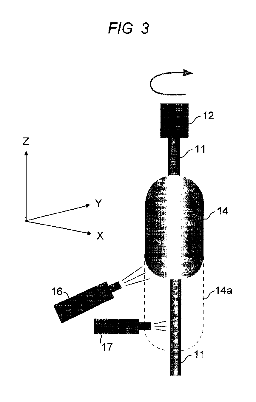
[0025]A soot preform was prepared using the dual torch arrangement shown in FIG. 3. The core rod was silica doped with 3.5% Ge. Pure silica soot was deposited while the core rod was pulled at a rate in the range 40-100 mm / hr. The pulling rate is automatically adjusted according to the growth rate of soot on the preform. The growth rate of soot is monitored by a laser that senses growth in the z-direction by directing a beam at the tip of the preform and measuring beam extinction. The pulling speed is measured by measuring the z-axis displacement of the pulling rod 12 in FIG. 3. The flow rate for SiCl4 was 1500 cc / min. Flow rates of the gases supplied to the deposition torch, including the fuel gases, will vary widely depending on the design of the apparatus used. The gas supply to cleaning torch 17 comprised the fuel gases hydrogen and oxygen, and 200 cc / min CF4. Refractive index profiles with preforms produced by this technique uniformly reflect sharp index transitions, and precise...

example 2

[0026]The same general method described in Example 1 was followed except that in this example the center core rod is pure silica and the soot deposited was fluorine doped. Again the result is sharp and controlled profiles.

[0027]After deposition of the soot and formation of the porous soot cladding layer, the porous layer is then consolidated by heating to a temperature sufficient to melt the silica particles (doped or undoped) into a solid, dense, glass preform. Consolidation is typically performed by heating the soot body to a temperature of 1400° C. to 1600° C. The solid preform is then ready for mounting in a fiber draw apparatus and drawing optical fiber, which will be discussed below.

[0028]The examples described are useful for producing a variety of types of preforms. It is especially well adapted for preparing core rods with a primary cladding layer. As indicated earlier, outside cladding may be made using other, less expensive, techniques. Accordingly, it is often useful to e...


PUM

PropertyMeasurementUnit
flow rateaaaaaaaaaa
temperatureaaaaaaaaaa
diameteraaaaaaaaaa

Abstract

The specification describes a VAD method for producing optical fiber preforms by depositing soot onto a solid core rod. The solid core rod preferably has a uniform composition, doped or undoped, suitable for the center core region of the preform. The primary cladding layer, and additional cladding layers if desired, are produced by depositing soot on the center core rod. The surface of the center core rod is treated with an etchant torch that traverses the center core rod in front of the soot deposition torch. This produces a clean interface between the core and primary cladding. This soot-on-center-core-rod method allows the production of sharp index profiles by reducing the diffusion of dopants into and out of the center core portion of the preform that occurs in soot-on-soot processes.

Description

FIELD OF THE INVENTION[0001]This invention relates to vapor axial deposition (VAD) processes for manufacturing optical fiber preforms.BACKGROUND OF THE INVENTION[0002]In a typical VAD process soot preforms are prepared by reacting glass precursors in an oxyhydrogen flame to produce silica particles. The silica particles are deposited on a starting rod. The starting rod is slowly pulled upward while it is rotated, and the silica particles are deposited axially on the rod as it is pulled. Very large, and long, soot preforms can be continuously fabricated. Typically the soot for the core is produced by a core torch and the soot for the cladding by a cladding torch. In this way, the composition of the glass can be varied from the center portion of the preform to the outside portion. Variation in glass composition is required for providing the refractive index difference necessary to produce light guiding in the optical fiber. After the soot is deposited, the preform is heated to consoli...

Claims


Application Information

Patent Timeline
Patent Type & Authority Patents(United States)
IPC IPC(8): C03B37/014
CPCC03B37/01446C03B37/0146C03B2201/04C03B2201/075C03B2201/32
Inventor WU, FENGQING
Owner FURAKAWA ELECTRIC NORTH AMERICA INC
Why Eureka
Try Eureka