
PC card motion detector

a motion detector and pc card technology, applied in the direction of electrical apparatus construction details, instruments, casings/cabinets/drawers, etc., can solve the problems of inadvertent removal of the wrong card, power will not have been properly discontinued from the card, and the removal of the computer card from the connector while the computer card is operating can have serious consequences on the operation of the computer system

Inactive Publication Date: 2005-08-09
IBM CORP
View PDF26 Cites 19 Cited by
  • Summary
  • Abstract
  • Description
  • Claims
  • Application Information

AI Technical Summary

Benefits of technology

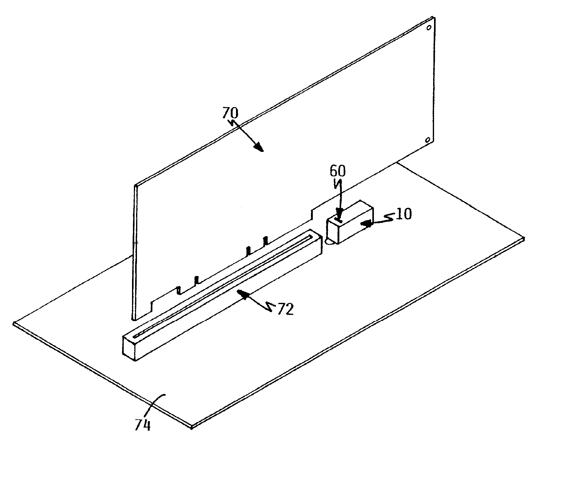
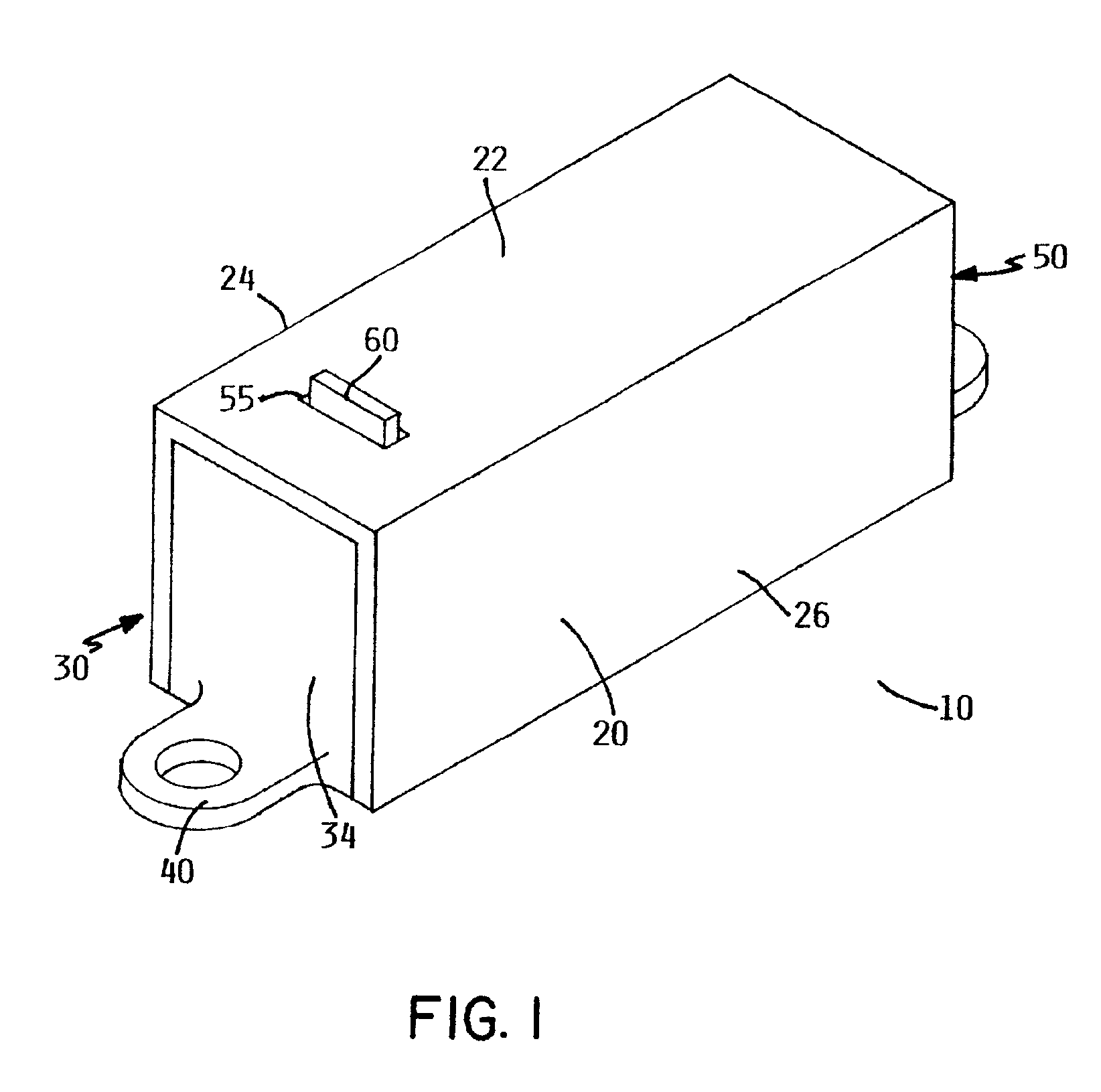
[0009]A first aspect of the invention is a detector with a sensor to detect motion of a computer module, and a switch to manage delivery of power to a connector holding the module. Initial motion of the module prior to disconnect of the card from the connector activates the switch. A sensor actuator is preferably provided to engage a shutter assembly actuator. A shutter assembly is preferably provided to communicate with the shutter assembly actuator and the switch. Actuation of the sensor preferably activates the shutter assembly actuator and vertically adjusts the shutter assembly to alter communication of the shutter assembly with the switch. The switch preferably sends a signal to a control circuit of the connector in response to movement of the shutter assembly. Preferably, the control circuit provides power to the connector when the shutter assembly is in communication with the switch and removes power from the connector when communication of the switch and the shutter assembly is removed. The sensor may be calibrated to detect motion of an adjacent computer module of about 0.005″. The switch may be optical, magnetic, or mechanical, and the actuator may be ratchet teeth, a pin, a magnet, or an electro-magnet.
[0010]A second aspect of the invention is a method for detecting motion of a computer module through a sensor. Power to a connector holding the module is disconnected upon motion of the module prior to disconnecting the module from the connector. The sensor preferably includes a shutter assembly in communication with a power switch of the connector. A signal is preferably sent to a control circuit of the connector in response to actuation of the sensor. The step of sending a signal to the control circuit preferably includes providing power to the connector when the shutter assembly is in communication with the switch and disconnecting power from the connector when communication of the shutter assembly with the switch is removed. The switch may be calibrated to detect motion of about 0.005″. The switch may be optical, magnetic, or mechanical, and the actuator may be ratchet teeth, a pin, a magnet, or an electro-magnet.

Problems solved by technology

One problem associated with hot swapping computer cards is the inadvertent removal of the wrong card.
When the wrong card is removed, the power will not have been properly discontinued from the card prior to removal of the card from the associated connector.
Removal of the computer card from the connector while the computer card is operating can have serious consequences on operation of the computer system.
For example, the system is likely to continue waiting on an uncompleted process involving the inadvertently removed card.
Such action can cause damage to both or either the computer card or the computer system in which the card has been operating.
Accordingly, the prior art system provides the ability to hot swap computer cards without providing adequate safety measurements to ensure removal of the proper card while the system is operating.
However, the mechanical switch is limited to a depressed position or a raised position.
The Klein et al. patent does not provide a switch that detects motion of the card that may occur outside the realm of insertion or removal of the card from the connector.
Accordingly, the mechanical switch in combination with the power switch does not provide the ability to remove power from the bus card during an initial movement of the card, such as movement associated with vibration.

Method used


Image

  • PC card motion detector
  • PC card motion detector
  • PC card motion detector

Examples


Embodiment Construction

Overview

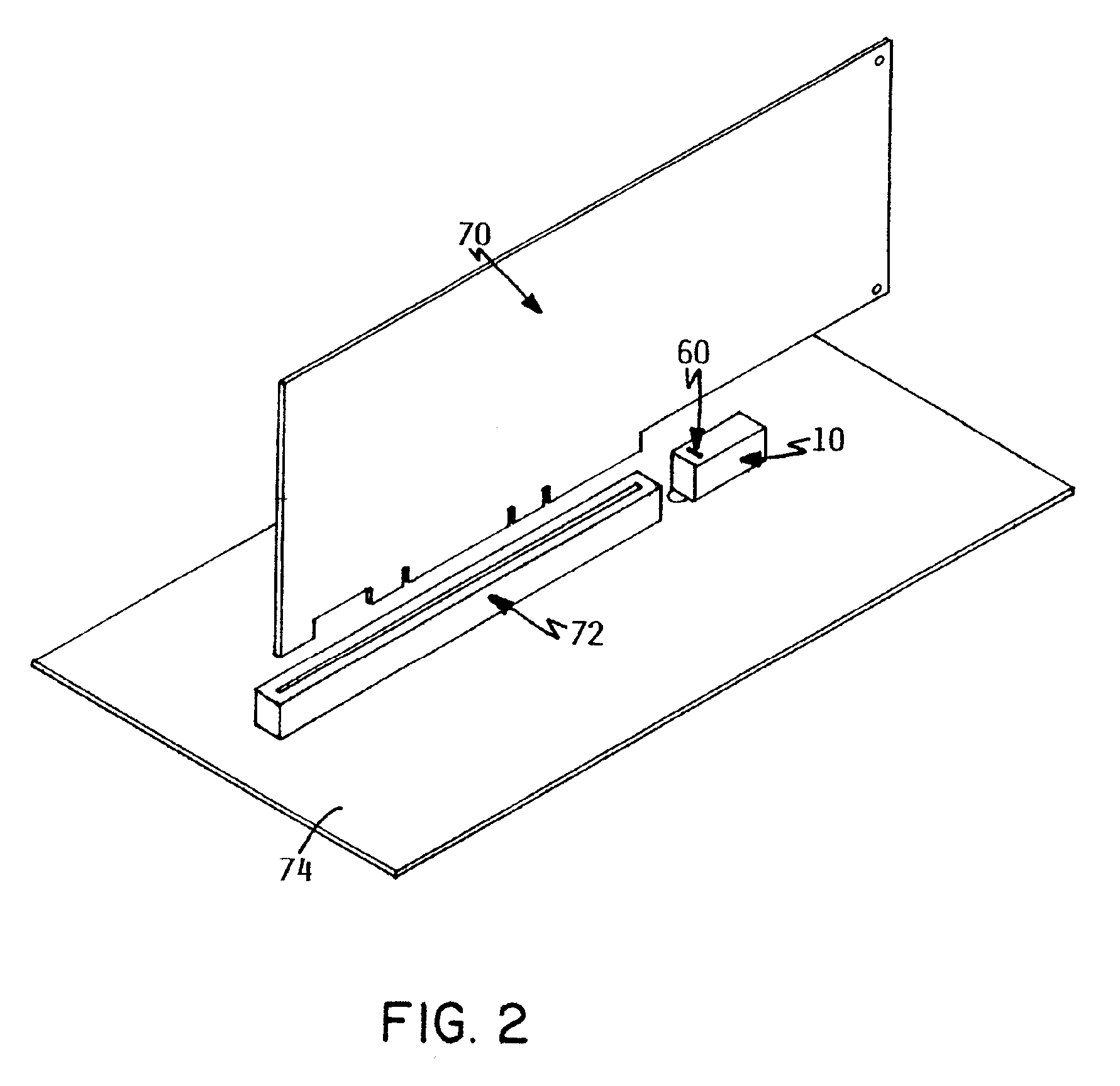
[0017]Computers and the associated motherboards are generally designed with a plurality of connectors for receiving computer cards. In general, most motherboards have the connectors aligned in a specific area. The computer case is complementary to the design of the motherboard so that the connectors of the motherboard are accessible from a specific area of the case. This enables an operator to hot swap computer cards without removing the case and exposing the motherboard. Alternatively, this enables an operator to secure any required accessories to a receiving end of the card. With recent advances in technology, motherboards are being configured to closely align computer cards. Accordingly, computer cards are arranged in such a manner that it is not uncommon to inadvertently remove a card that is still in operation in place of a card that has had power removed therefrom in anticipation of removal from the motherboard.

Technical Details

[0018]FIG. 1 is a perspective view of the...


PUM


Abstract

A motion detector is provided that enables power to a computer module to be disconnected prior to removal of the module from the connector. Actuation of a sensor causes a shutter assembly to move vertically. The shutter assembly is in communication with a switch. Movement of the shutter assembly causes actuation of the switch to send a signal to a control circuit of an associated controller. Power to the controller is provided when the shutter assembly is in communication with the switch, and power is removed from the connector when the shutter assembly is not in communication with the switch.

Description

BACKGROUND OF THE INVENTION[0001]1. Technical Field[0002]This invention relates to an apparatus to monitor movement of a computer system module. More particularly, the invention relates to a sensor for controlling power to an interface between the module and the computer system.[0003]2. Description of the Prior Art[0004]It has become common for computers to be serviced while performing regular functions. A typical computer includes a main board, also referred to as a “motherboard”, with a plurality of slots adapted to receive computer modules to expand the capacity and functionality of the computer. The demand for reliability in computer systems has led to the development of computer systems that support hot swapping of computer modules, including cards. This procedure allows a computer system to continue operating while a card is removed from the computer system or while a new card is inserted into the computer system. When one card is found to have a defective component or otherwi...

Claims


Application Information

Patent Timeline
Patent Type & Authority Patents(United States)
IPC IPC(8): G06F1/18
CPCG06F1/184G06F1/185G06F1/186
Inventor PEACOCK, JAMES LARRY
Owner IBM CORP
Learn More