
Liquid crystal display device, method for manufacturing the same, and electronic apparatus

a technology of liquid crystal display and electronic equipment, which is applied in non-linear optics, instruments, optics, etc., can solve the problems of deteriorating contrast, not improving contrast as much as expected, etc., and achieves high contrast display, reduce manufacturing costs, and efficient manufacturing process

Active Publication Date: 2005-08-09
BOE TECH GRP CO LTD
View PDF11 Cites 15 Cited by
  • Summary
  • Abstract
  • Description
  • Claims
  • Application Information

AI Technical Summary

Benefits of technology

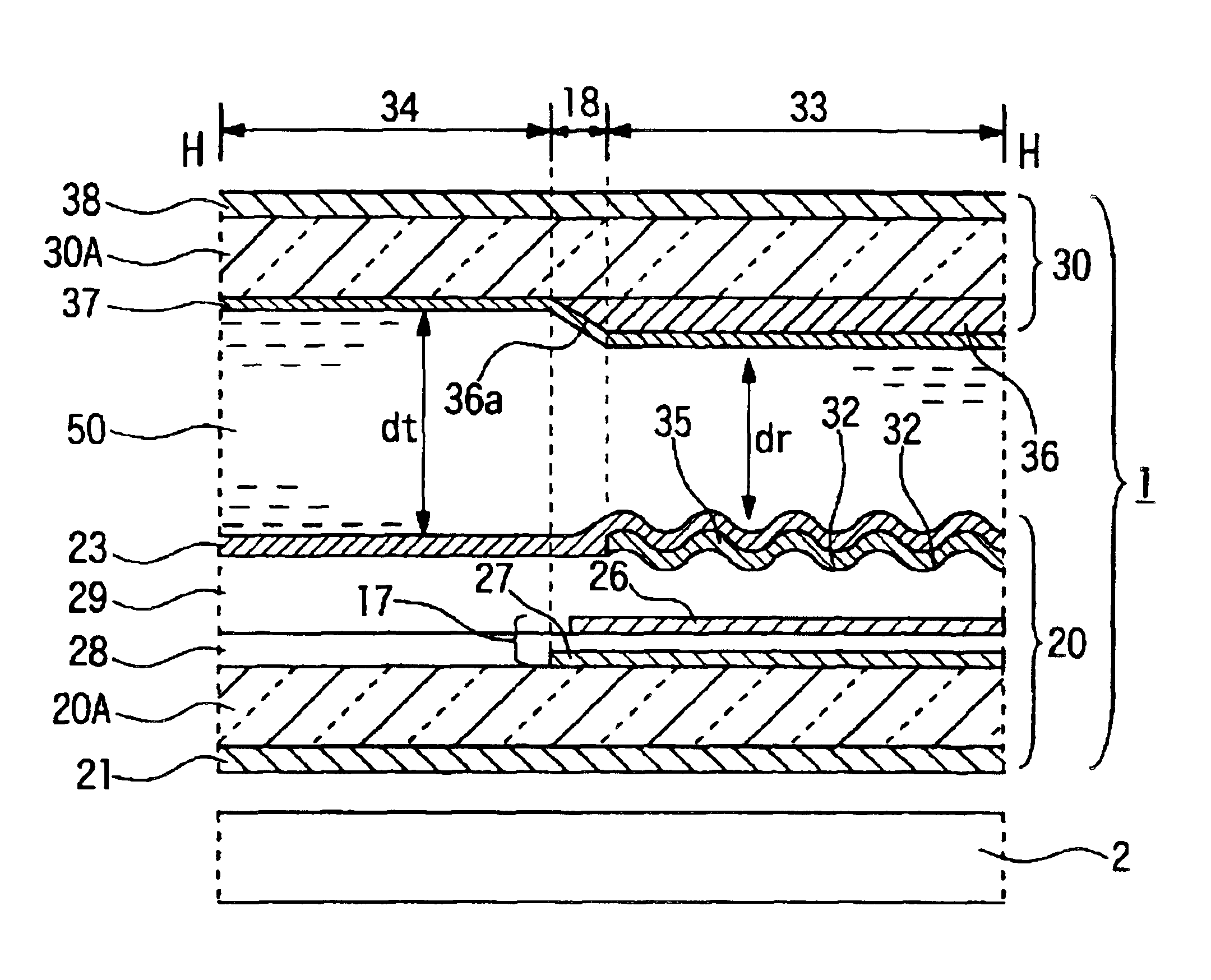
[0010]In the above liquid crystal display device 100, the reflection layer 111 is formed on the resin layer 112, whereby the thickness dr of the liquid crystal layer in the reflective display region 130 becomes thinner than the thickness dt of the liquid crystal layer in the transmissive display region 140. Thus, the device has an advantage that the optical path difference in between the regions can be adjusted to optimize the display luminance thereof. However, in the liquid crystal display device according to the above construction, as shown in FIG. 5, it is inevitable that an inclined part 170 is generated, due to the resin layer 112, between the reflective display region 130 and the transmissive display region 140. For this reason, there is a problem that leakage of light occurs due to disorder in alignment of liquid crystal molecules by the inclined part 170 and the contrast is not improved as much as expected. Further, FIG. 5 shows that an end of the reflection layer 111, which is provided on the resin layer 112, at the transmissive display region 140 side is arranged on the inclined part 170. In such an arrangement, the leakage of light can be reduced in the transmissive display, but the leakage of light occurs in the reflective display, and thus deteriorates the contrast. On the contrary, if the end of the reflection layer 111 is arranged not to reach the inclined part 170, the leakage of light occurs in the transmissive display, thereby deteriorating the contrast.
[0011]The present invention has been achieved in order to solve the above problems. Accordingly, an object of the present invention is to provide a transflective liquid crystal display device having a transmissive display region and a reflective display region in one dot region, and capable of achieving a bright and high-contrast display in both the reflective display and the transmissive display.

Problems solved by technology

For this reason, there is a problem that leakage of light occurs due to disorder in alignment of liquid crystal molecules by the inclined part 170 and the contrast is not improved as much as expected.
In such an arrangement, the leakage of light can be reduced in the transmissive display, but the leakage of light occurs in the reflective display, and thus deteriorates the contrast.

Method used


Image

  • Liquid crystal display device, method for manufacturing the same, and electronic apparatus
  • Liquid crystal display device, method for manufacturing the same, and electronic apparatus
  • Liquid crystal display device, method for manufacturing the same, and electronic apparatus

Examples


Embodiment Construction

[0032]Hereinafter, embodiments of the present invention will be described with reference to the drawings.

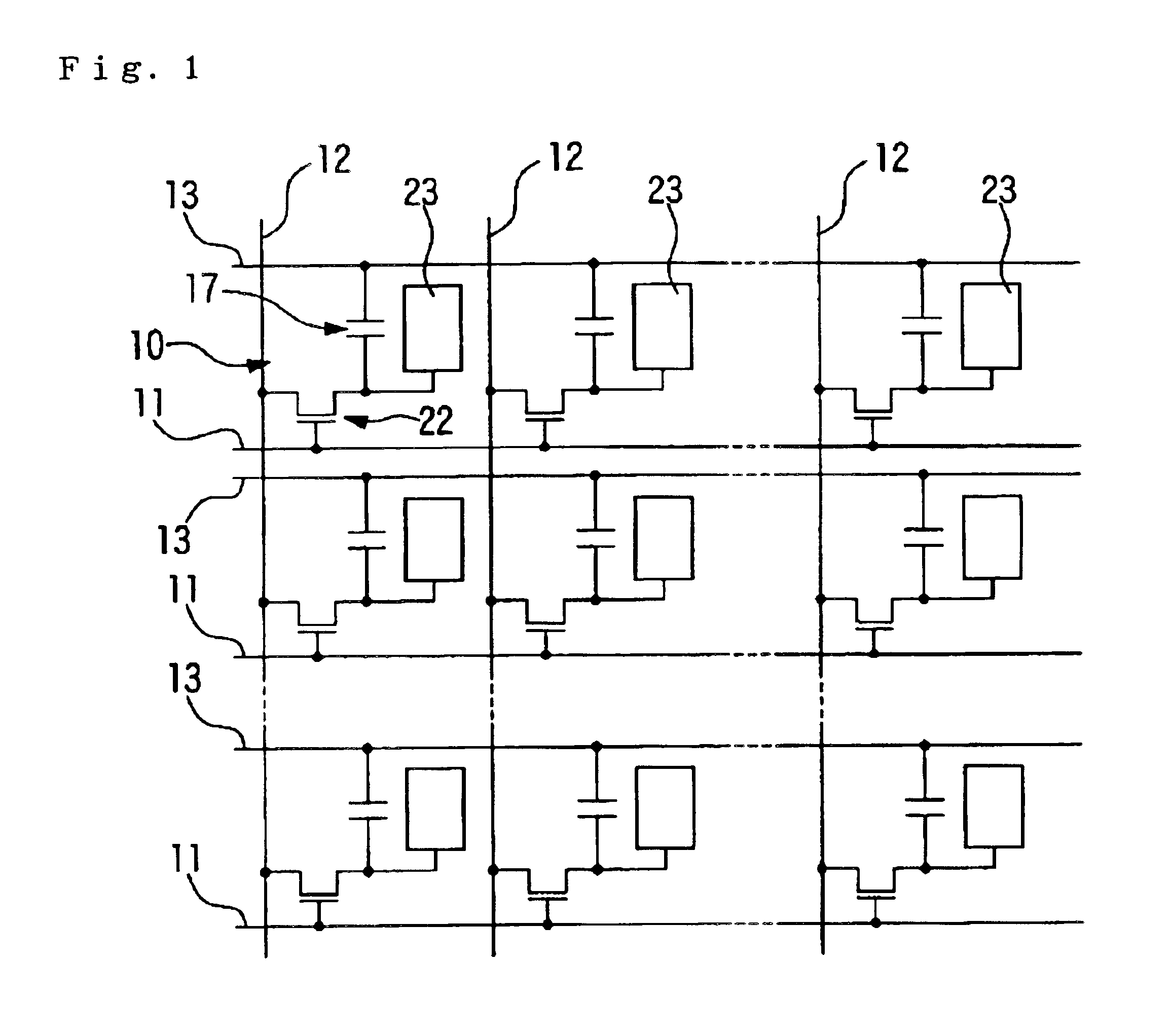
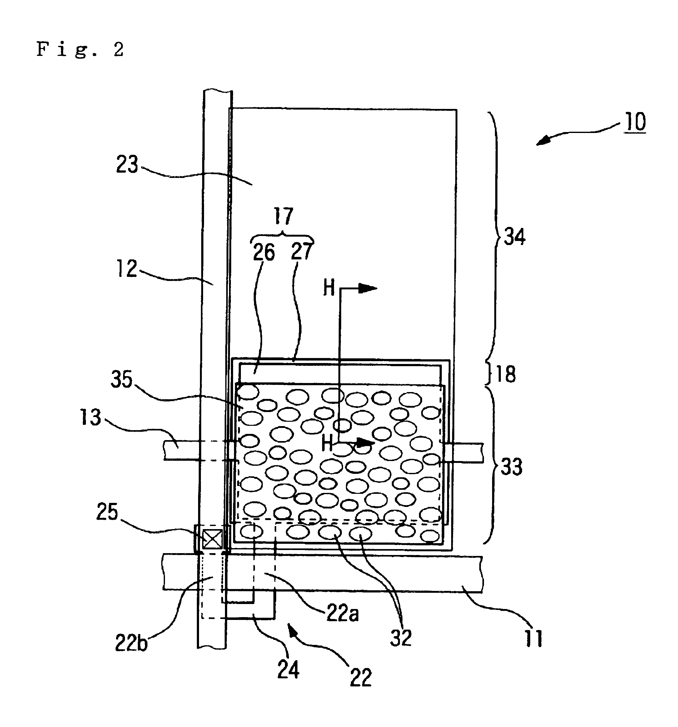
[0033]FIG. 1 is an explanatory view illustrating an exemplary wiring structure of a plurality of pixels, which are formed in a matrix, constituting an active matrix type liquid crystal display device, according to an embodiment of the present invention. FIG. 2 is a plan view of a construction of a dot region 10 shown in FIG. 1, when seen from the display surface side. FIG. 3 is a cross-sectional view taken along the line H—H shown in FIG. 2. As shown in FIG. 2 and FIG. 3, the liquid crystal display device of this embodiment is a transflective liquid crystal display device comprising a liquid crystal panel 1 having a reflective display region 33 and a transmissive display region 34 in one dot region, and an inclined region 18 between the display regions 33 and 34, and a backlight (illuminator) 2 arranged on the backside thereof.

[0034]As shown in FIG. 1, the liquid crystal display ...


PUM


Abstract

The invention provides a liquid crystal display device having a transmissive display region and a reflective display region in one dot region, and capable of obtaining a bright and high-contrast display in both a reflective display and a transmissive display. In particular, a liquid crystal display device according to the present invention can include a reflective display region and a transmissive display region provided in one dot region, and a reflection layer provided in the reflective display region. A pixel electrode, a TFT element for driving the pixel electrode, a capacitive electrode connected to the pixel electrode, an electrode part arranged to oppose the capacitive electrode via an insulating layer are formed in the dot region. Further, in the display regions within the dot region, the capacitive electrode or the capacitive line can be arranged at a position where it overlaps, in plan view, the inclined region between the reflective display region and the transflective display region.

Description

BACKGROUND OF THE INVENTION[0001]1. Field of Invention[0002]The present invention relates to liquid crystal display devices and electronic apparatuses. More specifically, the invention relates to a construction of a transflective liquid crystal display device capable of performing display with sufficient brightness, in particular, even in a transmission mode.[0003]2. Description of Related Art[0004]A transflective liquid crystal display device which performs a display both in a reflective display mode and a transmissive display mode, can perform a clear display even in dark surroundings while reducing the power consumption by switching its display mode between the reflection mode and the transmission mode depending on the ambient brightness.[0005]There has been proposed a transflective liquid crystal display device in which a liquid crystal layer is interposed between light transmissive upper and lower substrates, and a reflection film, which is made of a metal film such as aluminum...

Claims


Application Information

Patent Timeline
IPC IPC(8): G02F1/13G02F1/1335G02F1/1333G02F1/1362G02F1/1343G02F1/1368
CPCG02F1/133555G02F1/133371G02F1/136213G02F1/1343
Inventor ITOH, TOMOYUKIOZAWA, TOKURO
Owner BOE TECH GRP CO LTD
Learn More