
System bridge and timeclock for RF controlled lighting systems

a technology of lighting control system and time clock, which is applied in the direction of electric controllers, ignition automatic control, instruments, etc., can solve the problems of increasing costs, requiring complicated and/or cumbersome retrofitting, and reducing so as to minimize message collisions and avoid data collisions. , the effect of minimizing the possibility of subnet communication

Inactive Publication Date: 2005-08-09
LUTRON TECH CO LLC
View PDF8 Cites 137 Cited by
  • Summary
  • Abstract
  • Description
  • Claims
  • Application Information

AI Technical Summary

Benefits of technology

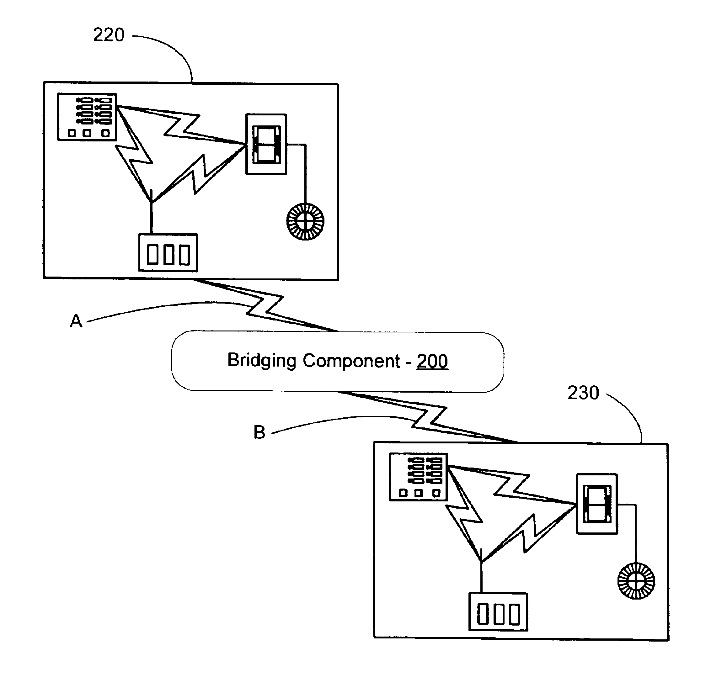
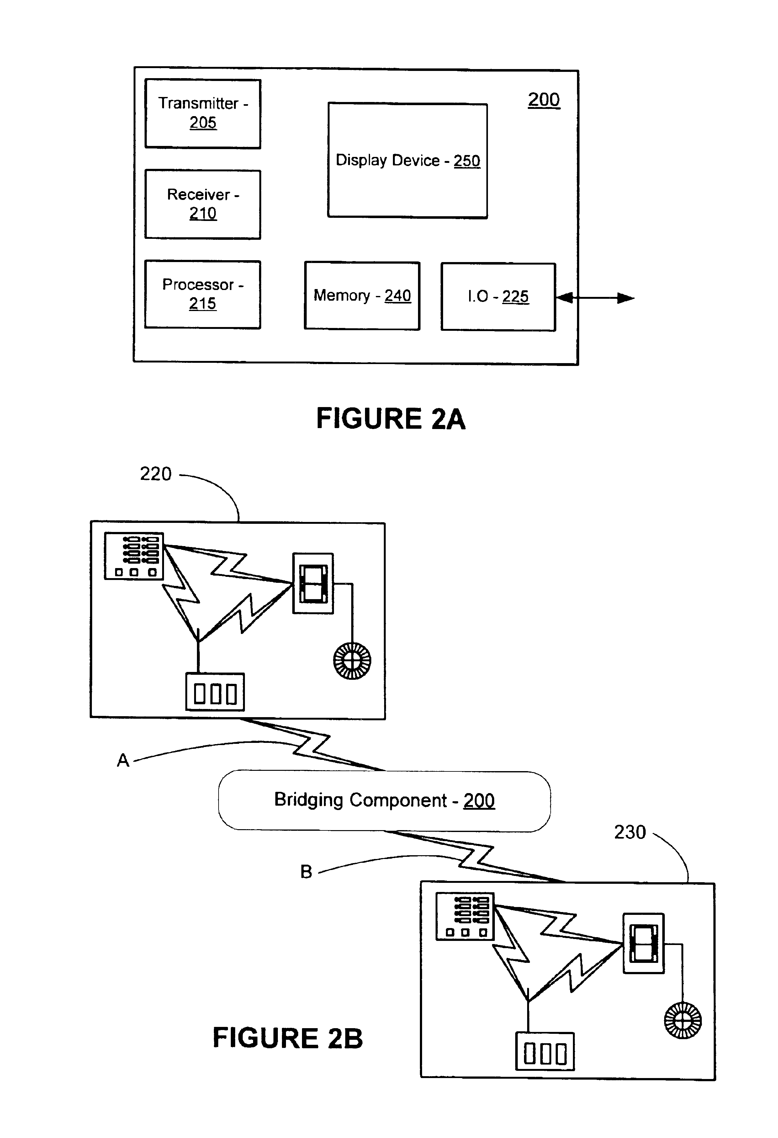
[0010]In view of the above shortcomings, a bridging device and method is described that provides a link between lighting networks, called subnets, which are operating on the same RF while in close proximity to each other. In an embodiment of the present invention, a bridge between two or more subnets is provided that allows each subnet to receive and transmit RF signals, or messages, to devices within the subnet or to other subnets while minimizing message collisions. An embodiment therefore permits the control of programmable lighting scenes involving lighting devices controlled by multiple subnets. Another embodiment of the present invention relates to the method of communication employed to convey information between multiple subnets.
[0011]In an embodiment of the present invention, two or more closely located subnets are provided, wherein each subnet is operating on the same RF. An embodiment enables each subnet to communicate with each other while allowing for some overlapping control between subnets by way of a master control. Accordingly, an embodiment of the present invention allows global capability through the programming and operation of, for example, phantom buttons operatively connected to the bridging device. An embodiment also minimizes the possibility of the subnets communicating simultaneously, thereby avoiding data collisions.
[0012]An embodiment of the present invention expands the number of devices that can be controlled and operated with the use of a master control panel. For example, in a RadioRA® system, the controllable devices can be increased from 32 to 64 controllable devices. In other embodiments, a different number of devices may be controlled.

Problems solved by technology

In either case, the planning for and installation of a wired system requires effort that increases costs.
The cost savings of wireless systems is especially noticeable in older, existing buildings that would otherwise require complicated and / or cumbersome retrofitting.
As a result, however, it is possible that the devices within a subnet may interfere with each other as a result of transmitting at the same time on the same frequency.
In addition, in existing RF lighting control systems there is a limitation as to the number of devices that can be controlled on a single network.
Too great a number of devices will run afoul of FCC regulations because such regulations permit transmissions of only a certain length of time on a particular frequency.
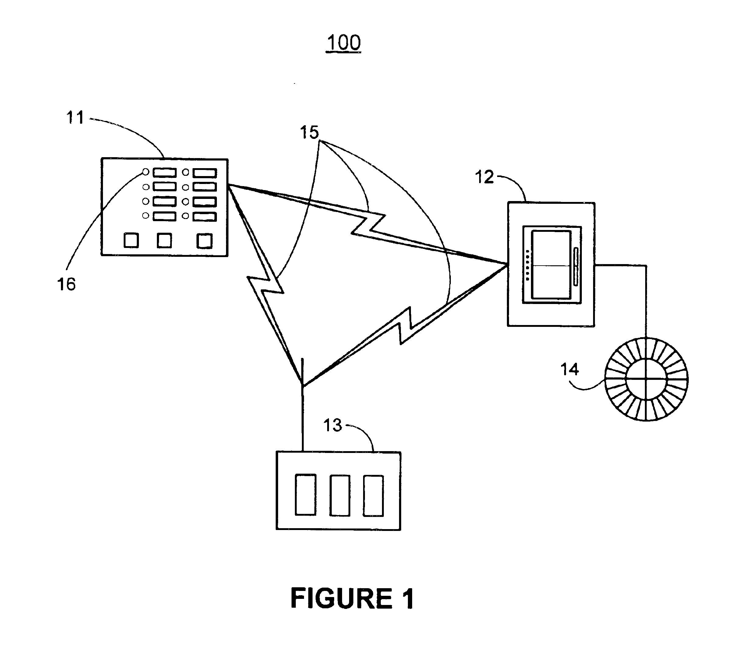
It will be appreciated that placing two wireless lighting control systems in close proximity to each other when both are operating on the same frequency poses serious problems, particularly when a lighting scene involves both subnets.
Specifically, it is possible that the individual subnets will communicate simultaneously and therefore would interfere with each other by causing messages to collide and by unnecessarily populating the RF.
For example, when two unrelated subnets are located in close proximity, each subnet runs a risk of interfering with the other.
However, because each subnet is unrelated, the timing of lighting events—such as a scene—in each subnet will only occur at the same time as a coincidence.
As a result, in multiple subnet systems, the RF transmission times increase to the point that interference is likely.

Method used


Image

  • System bridge and timeclock for RF controlled lighting systems
  • System bridge and timeclock for RF controlled lighting systems
  • System bridge and timeclock for RF controlled lighting systems

Examples


Embodiment Construction

[0022]An embodiment of the present invention relates to operatively interconnecting two or more RF lighting control systems that are operating in close proximity to each other on the same RF. Close proximity in such an embodiment refers to the ability of at least one device of one RF lighting control system to transmit a RF signal that may be received by at least one device of a second RF lighting control system. As may be appreciated, the RF signals used by such lighting control systems may be of any frequency that is suitable for the intended location and use of the lighting control system. For example, the frequency may be chosen to comply with FCC regulations, to avoid interference with other devices located in the area in which the lighting control system is operating, or in accordance with other considerations.

[0023]As noted above, an embodiment of the present invention relates to lighting control systems that may be employed in buildings or the like. Examples of such lighting...


PUM


Abstract

A method for operatively interconnecting a first and second lighting control subnet is disclosed. In the method, a link claim is transmitted to the first and second lighting control subnets from a bridge. The link claim directs the first and second lighting control subnets to wait for a lighting control command, which is transmitted to the lighting control command to the first lighting control subnet. A random wait time is assigned to the first lighting control subnet and a maximum random wait time is assigned to the second lighting control subnet. Finally, an acknowledgement is received from the first lighting control subnet.

Description

RELATED APPLICATIONS[0001]This application claims the benefit of U.S. application Ser. No. 60 / 477,505, filed Jun. 10, 2003, titled System Bridging Timeclock for RF Controlled Lighting Systems.FIELD OF THE INVENTION[0002]The present invention relates generally to lighting control systems. More particularly, the present invention relates to interconnecting lighting control systems, where the lighting control systems are operating at the same Radio Frequency (RF). Even more particularly, the present invention relates to a device and method for such interconnection.BACKGROUND OF THE INVENTION[0003]Lighting applications can be implemented with a combination of predetermined lighting devices operating at predetermined light intensity levels. For example, a residential lighting application may require a variety of lighting scenarios, or “scenes.” A first scene may be needed for when the residents are at home and active within the house. In such a scene, lights at various locations may be i...

Claims


Application Information

Patent Timeline
Patent Type & Authority Patents(United States)
IPC IPC(8): H05B37/02
CPCH05B37/0272H05B47/19
Inventor WALKO, JR., ROBERT FRANCISKEAGY, JON MICHAELCRAZE, JASON DOUGLASSKRUSE, GLEN ANDREW
Owner LUTRON TECH CO LLC
Learn More