
Assembly structure of case and the assembling method therefor

a technology of assembly structure and assembly method, which is applied in the direction of electrical apparatus casing/cabinet/drawer, lighting conductor installation, coupling device connection, etc., can solve the problems of lack of gloss, deformation, and shade of plastic injection molding products, and achieve the effect of reducing the formation of shade, increasing the creepage distance of the assembled case, and improving the appearance and electric properties of the cas

Active Publication Date: 2005-08-09
DELTA ELECTRONICS INC +1
View PDF6 Cites 29 Cited by
  • Summary
  • Abstract
  • Description
  • Claims
  • Application Information

AI Technical Summary

Benefits of technology

The present invention provides an assembly structure of a case for electronic apparatus or accessories that can decrease the formation of shade or flow mark on the case and improve the appearance and electrical properties of the electronic apparatus or accessories. The assembly structure includes an upper case and a lower case that are assembled together using a connection portion with a first cavity, a first protrusion, a first trench, and a second protrusion. The first and second protrusions have protruding ribs that fit into corresponding cavities in the upper case and lower case, respectively. The assembly structure can be formed using injection molding or other methods. The technical effects of the invention include reducing the appearance of shade or flow mark on the case, improving the appearance of the electronic apparatus or accessories, and increasing the creepage distance between the case and the assembled components.

Problems solved by technology

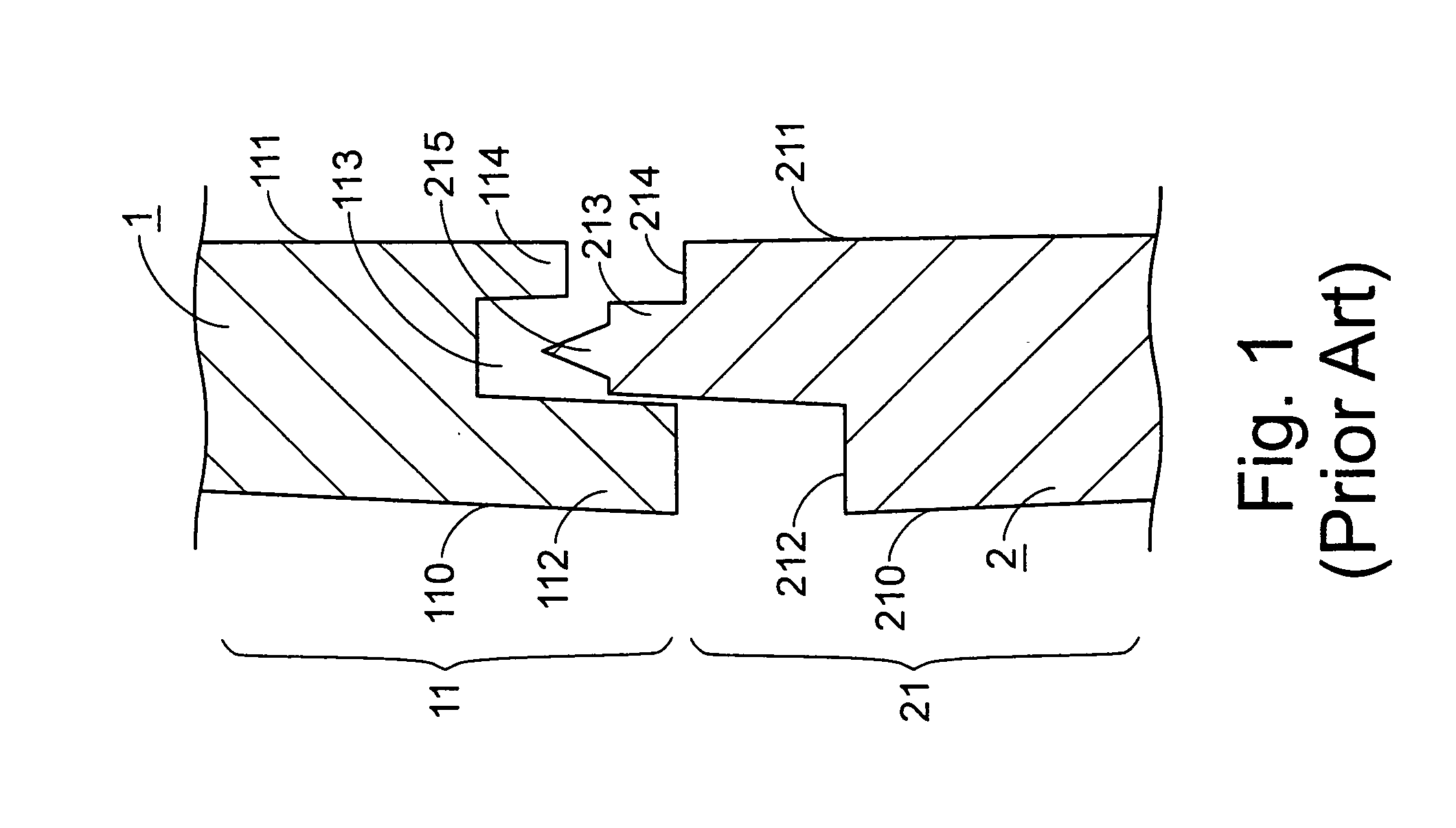
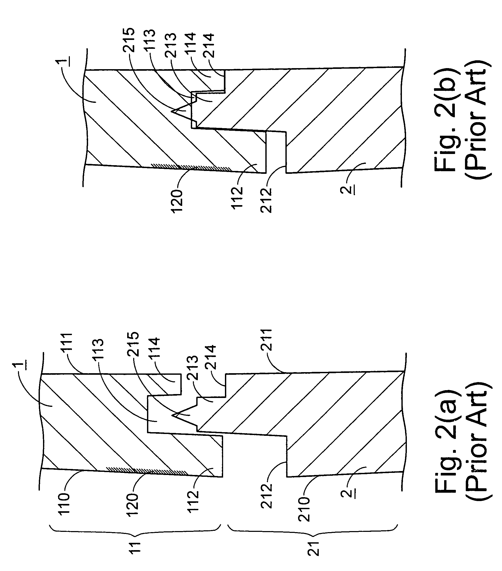
As known by one skilled in the art, the products made from plastic injection molding usually have disadvantages of fracture, shade or flow mark, lack of gloss, or deformation and so on.
In which, the reason that causes the formation of flow mark on the product of plastic injection molding includes: the material is not welded well; the temperature of the mode is too low; the injection rate is too fast or too slow; the injection pressure is too high or too low; or the thickness difference on the cross-section of the product is too large.
The reason that causes the formation of shade on the product is the wall thickness of the connection portion of the case is uneven.
Since the shade or flow mark will influence the appearance of the assembled case, how to reduce the formation of shade or flow mark is an important issue.

Method used


Image

  • Assembly structure of case and the assembling method therefor
  • Assembly structure of case and the assembling method therefor
  • Assembly structure of case and the assembling method therefor

Examples


Embodiment Construction

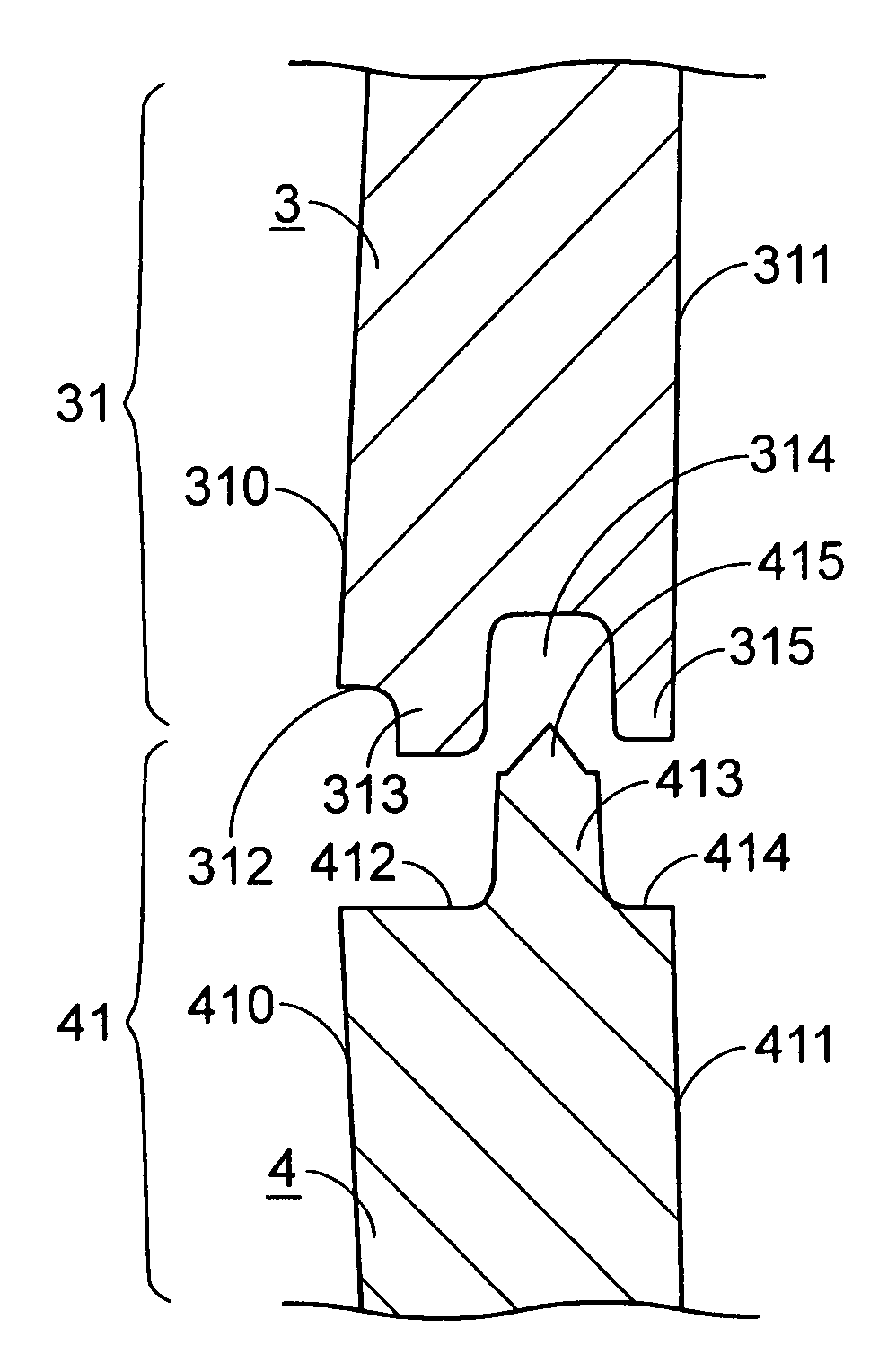
[0029]Please refer to FIG. 3, which is a schematic view showing the assembly structure of a case according to a preferred embodiment of the present invention. As shown in FIG. 3, the assembly structure of the case of the present invention is composed of an upper case 3 and a lower case 4. The upper case 3 has a connection portion 31 including a first cavity 312, a first protrusion 313, a first trench 314 and a second protrusion 315 arranged from the external side 310 to the internal side 311 of the upper case 3. The lower case 4 also has a connection portion 41 including a first cavity 412, a first protrusion 413 and a second cavity 414 arranged from the external side 410 to the internal side 411 of the lower case 4. In this embodiment, both the first cavity 312 and the first protrusion 313 of the upper case 3 are opposite to the first cavity 412 of the lower case 4 and their widths are approximately equal. Furthermore, the first trench 314 and the second protrusion 315 of the upper...


PUM


Abstract

An assembly structure of a case is disclosed. The assembly structure includes an upper case and a lower case. The upper case has a connection portion having a first cavity, a first protrusion, a first trench and a second protrusion arranged from the external side to the internal side thereof. The lower case has a connection portion having a first cavity, a first protrusion and a second cavity arranged from the external side to the internal side thereof. Both the first cavity and the first protrusion of the upper case are opposite to the first cavity of the lower case, and the first trench and the second protrusion of the upper case are opposite to the first protrusion and the second cavity of the lower case, respectively, so as to assemble the upper case and the lower case.

Description

FIELD OF THE INVENTION[0001]The present invention relates to an assembly structure of a case and the assembling method therefor, and more particularly to an assembly structure of a case and the assembling method therefor which can decrease the formation of shade or flow mark on the case and increase the creepage distance of the assembled case.BACKGROUND OF THE INVENTION[0002]In our daily life, various electronic apparatuses and their accessories, such as power adapters, connectors, power supplies, plugs or sockets, etc., are widely used. Since the internal electronic elements and circuits of these electronic apparatuses or accessories need to be appropriately isolated and protected, they are covered by cases to avoid the contact with the external environment. The assembly structure of the case and the assembling method therefor will indirectly influence the appearances and the electrical properties of the electronic apparatuses or accessories, so it is important to design an appropr...

Claims


Application Information

Patent Timeline
Patent Type & Authority Patents(United States)
IPC IPC(8): H02G3/08
CPCH02G3/081H02G3/088H05K5/066
Inventor LIM, CHOO SOOKITTI, SAE-UENGCHEN, CHUN-CHEN
Owner DELTA ELECTRONICS INC
Learn More