
Portable x-ray table

a x-ray table and portability technology, applied in the field of boards or tables, can solve the problems of affecting the patient's health, causing pain, causing harm or even death, and allowing the patient to move freely

Inactive Publication Date: 2005-08-09
STOUT JR FRED T
View PDF16 Cites 18 Cited by
  • Summary
  • Abstract
  • Description
  • Claims
  • Application Information

AI Technical Summary

Benefits of technology

[0004]It is an object of the present invention to provide a portable table on which a patient can be placed for the taking of one or more x-rays without unnecessary movement of the patient's body.
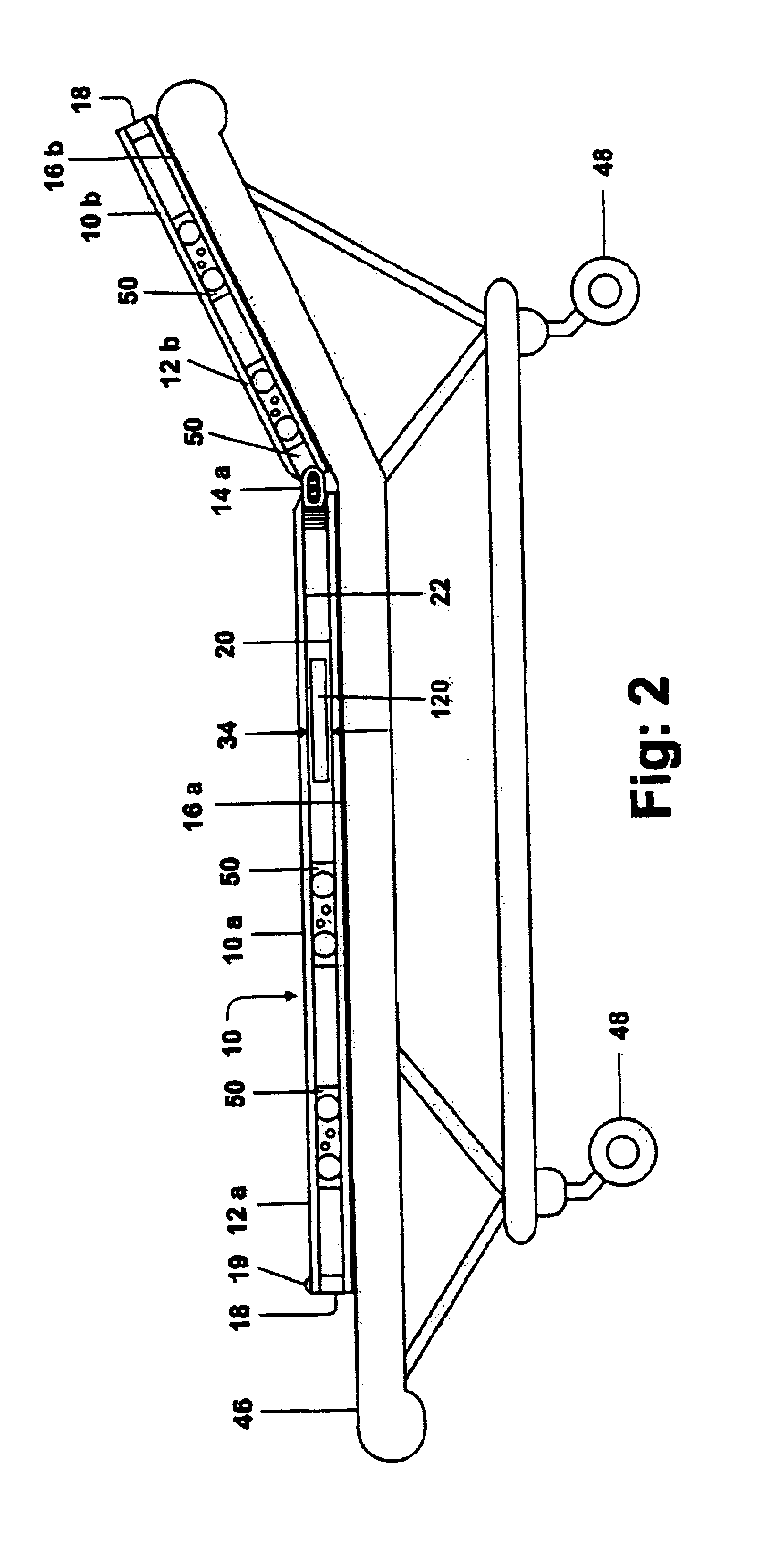
[0007]The invention relates to an x-ray table that comprises a top planar support made from a substantially radiolucent material and is adapted to receive the body of a patient. A rigid planar base is parallel to the top support and is spaced therefrom to form a slot or gap adapted to receive an x-ray plate. At least one trolley is positioned between the top support and the base, and is moveable therebetween. The base is equipped with means, such as wheels, rollers or slides, that permit the trolley to be easily rolled or slid into proximity of the location where the x-ray plate is to be inserted. The trolley serves to maintain adequate spacing between the base and the top support. This allows the plate to be freely inserted and withdrawn without the weight of the patient compressing the gap between the top support and the base. The support and the base typically are rectangular in shape, defining two generally parallel opposed sides, a head and a foot. The base includes a guide along at least one of the opposed sides, in the form of one or more, preferably two, grooves that define a path along which the trolley rolls or slides.

Problems solved by technology

Such movement of a patient can be painful, harmful or even fatal.
Attendant with this is the possibility of further injury to the patient as previously noted.

Method used


Image

  • Portable x-ray table
  • Portable x-ray table
  • Portable x-ray table

Examples


Embodiment Construction

[0017]Turning now to FIGS. 1 and 2, an x-ray table 10 of the present invention is shown, composed of a larger section 10a and a smaller section 10b joined to one another by strap hinges 14a and 14b. Each portion 10a, 10b comprises a top support 12a, 12b of a flat, rigid material that preferably is radiolucent and a base 16a, 16b. By radiolucent is meant that the material is easily penetrated by x-rays, while at the same time being substantially visually transparent.

[0018]The two portions of the top support 12a, 12b are sufficiently rigid, preferably, to permit medical personnel to perform resuscitation or other lifesaving techniques on a patient lying on the table 10. Typically, the top support is constructed of a transparent plastic, such as Plexiglas® acrylic plastic or Lexan® polycarbonate, or a material such as acrylonitrile butadiene-styrene or acrylic polyvinylchloride, and is sufficiently thick so that it maintains rigidity under the weight of a patient's body. Typically, the...


PUM


Abstract

An articulated x-ray table comprises a planar, rigid radiolucent top support and a base spaced therefrom to form a gap whereby radiographic plates can be inserted and withdrawn. The gap is maintained by the use of one or more trolleys that are moveable along the length of the table to be moved into proximity to the location where the plate is to be inserted. Generally, two of the trolleys are used along either side of the table for placement near the x-ray plate. The trolleys move in grooves or tracks on the edges of the base along the length of the table. Each trolley includes wheels that engage the grooves, and a separate roller that engages the top support. This permits the trolleys to be easily moved along the guide notwithstanding the weight of a patient on the table. The table can be used for animals and humans.

Description

FIELD OF THE INVENTION[0001]This invention relates generally to the field of boards or tables for supporting the human body, or that of an animal, while allowing for x-rays or other radio-images to be taken of the patient.BACKGROUND OF THE INVENTION[0002]X-ray examinations are often a first step in the treatment of persons or animals that have undergone trauma that possibly has resulted in one or more broken or displaced bones. It is well known to those in the medical profession that an emergency room patient is often moved to an x-ray table for such an examination, after which the patient is then again moved from the table to another location for the next step of diagnosis or treatment. Even if the patient is not transferred from table to table, the patient must often be turned, or otherwise moved, to permit an x-ray plate to be positioned at the right location for the x-ray to be taken. When the x-ray plate must be placed beneath the patient for examination, this requires lifting ...

Claims


Application Information

Patent Timeline
IPC IPC(8): A61B6/04
CPCA61B6/04A61B6/4283A61B6/4423A61B6/548A61B6/508
Inventor STOUT, JR., FRED T.
Owner STOUT JR FRED T
Learn More