
Aircraft with thrust vectoring for switchably providing upper surface blowing

a technology of upper surface and thrust vector, which is applied in the direction of vertical landing/take-off aircraft, aircraft navigation control, transportation and packaging, etc., can solve the problems of exhaust flow not providing upper surface blowing, exhaust flow not providing surface blowing, etc., and achieve the effect of lifting

Inactive Publication Date: 2005-08-09
THE BOEING CO
View PDF14 Cites 31 Cited by
  • Summary
  • Abstract
  • Description
  • Claims
  • Application Information

AI Technical Summary

Benefits of technology

The patent describes a method and apparatus for operating a jet engine on a mobile platform, such as an aircraft or a wing, to provide surface blowing to augment lift. The engine can be controlled to direct the exhaust flow either across the surface of the lift-producing surface or downstream, depending on the operating phase of the mobile platform. The technical effect of this invention is to improve the performance and efficiency of the jet engine on a mobile platform by optimizing the exhaust flow direction for different operating phases.

Problems solved by technology

The engine is positioned relative to the lift-producing surface such that the exhaust flow does not provide surface blowing when the second configuration is used.
The engine is positioned relative to the airfoil such that the exhaust flow does not provide surface blowing when the exhaust flow is vectored to flow generally downstream.
The engine is positioned relative to the wing such that the exhaust flow does not provide upper surface blowing when the nozzle is in the second configuration.
The engine is positioned relative to the wing such that the exhaust flow does not provide upper surface blowing when the engine is in the second configuration.

Method used


Image

  • Aircraft with thrust vectoring for switchably providing upper surface blowing
  • Aircraft with thrust vectoring for switchably providing upper surface blowing
  • Aircraft with thrust vectoring for switchably providing upper surface blowing

Examples


Embodiment Construction

[0021]The following description of the preferred embodiment(s) is merely exemplary in nature and is in no way intended to limit the invention, its application, or uses.

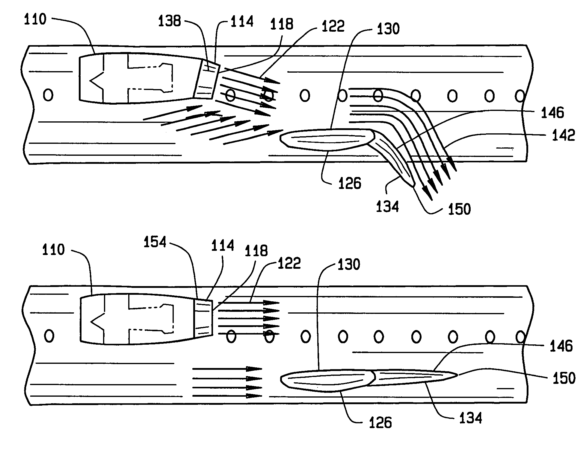
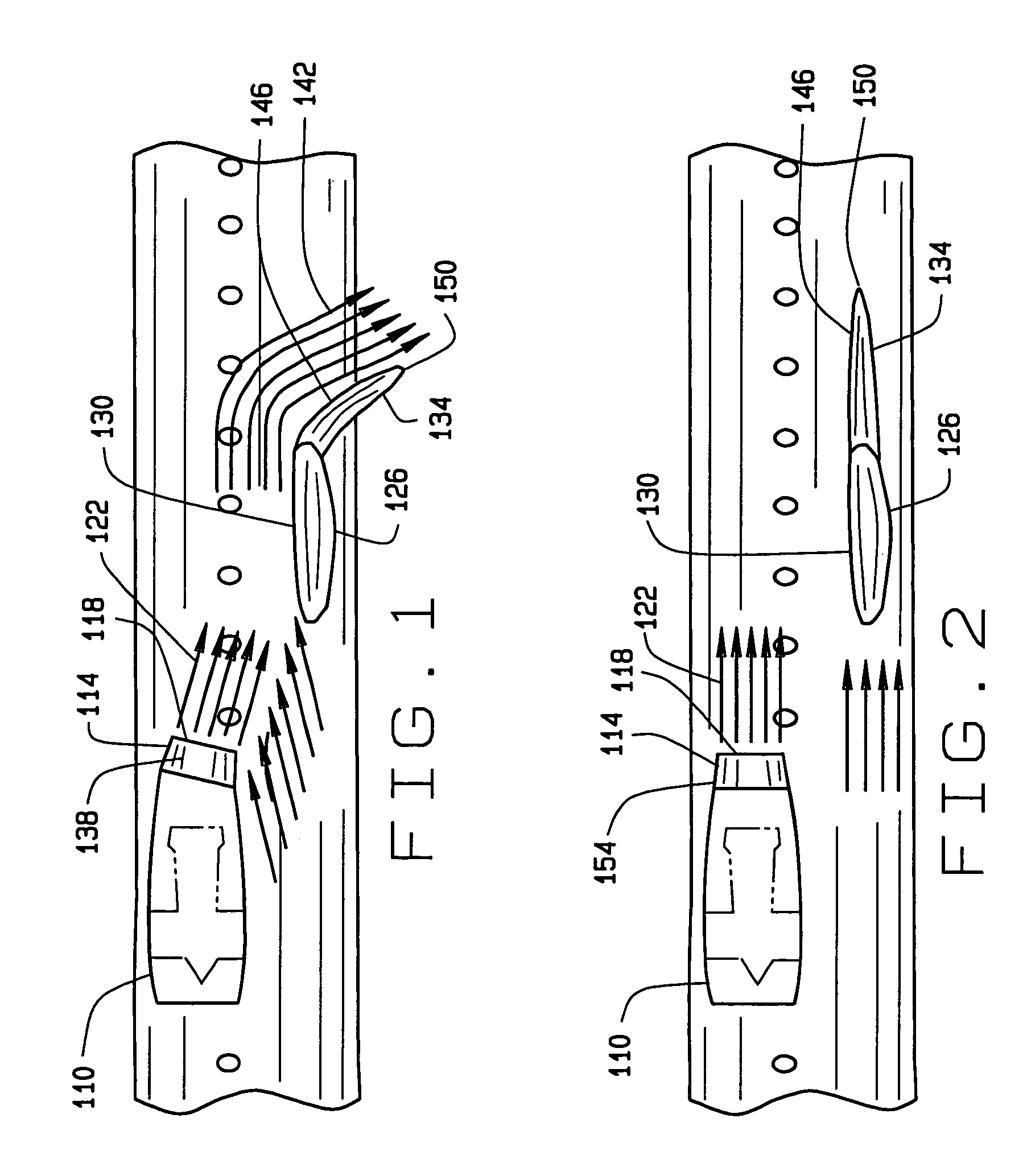
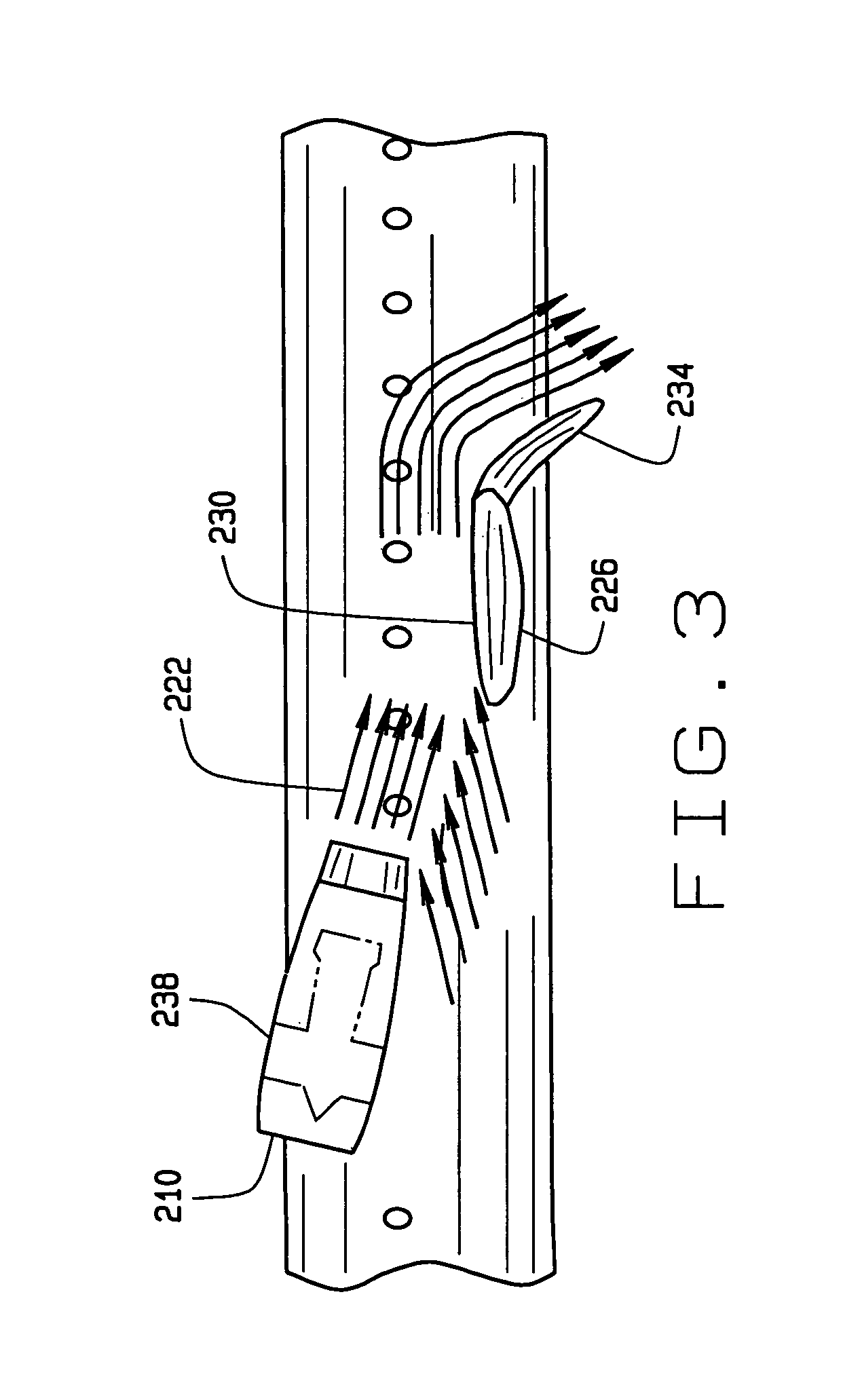
[0022]According to one aspect of the invention, thrust vectoring is used to switchably provide upper surface blowing (USB). By controllably changing the thrust vector of an exhaust flow generated by an engine, upper surface blowing can be “switched” on or off depending on the particular operating phase of the aircraft. For example, the exhaust flow can be vectored (FIGS. 1 and 3) to provide upper surface blowing to augment wing lift when relatively high lift is required, such as during short takeoff and landing (STOL) operations. During cruise, however, the exhaust flow can be discharged so that it does not provide upper surface blowing (i.e., USB switched off) (FIG. 2). In which case, the aircraft's cruise performance is unaffected by exhaust flow “scrubbing” the upper wing surface and drag produced there from. Indee...


PUM


Abstract

Aircraft having thrust vectoring for switchably providing upper surface blowing. The aircraft generally includes a wing and an engine. The engine can be rotatably supported to supporting structure to allow the engine to be controllably rotated relative to the wing, and / or the engine can include a thrust vectoring nozzle. The engine's thrust vectoring capabilities allow the exhaust flow to be controllably vectored to switch on or off upper surface blowing depending on the aircraft's phase of operation. During a first phase, the exhaust flow can be vectored to flow across the upper wing surface to provide upper surface blowing to augment lift. During a second phase, the exhaust flow can be discharged generally downstream or rearwardly. The engine is positioned relative to the wing such that the exhaust flow does not provide upper surface blowing during the second phase.

Description

FIELD OF THE INVENTION[0001]The present invention generally relates to aircraft which utilize upper surface blowing to augment wing lift, and more particularly to aircraft having thrust vectoring for switchably providing upper surface blowing which can be switched on or off.BACKGROUND OF THE INVENTION[0002]Many central hub airports for commercial airline carriers suffer from high traffic and runway congestion. There has been an increasing interest in short takeoff and landing (STOL) aircraft as a possible means for alleviating airport congestion. Because STOL aircraft can take advantage of the alternate shorter runways that generally coexist alongside longer counterpart runways, STOL aircraft can help combat airport congestion. Not only will STOL aircraft allow for an increased number of flights from congested airports, they will also increase the number of accessible airports.[0003]Although existing STOL aircraft have worked well for its intended purposes including allowing shorter...

Claims


Application Information

Patent Timeline
Patent Type & Authority Patents(United States)
IPC IPC(8): B64C15/00B64C15/02B64C15/12B64D27/20B64D27/00
CPCB64C15/02B64C15/12B64D27/20
Inventor CUMMINGS, DAROLD B.KUTZMANN, AARON J.DRONEY, CHRISTOPHER K.
Owner THE BOEING CO
Learn More