
Combination needle for peripheral nerve block

Inactive Publication Date: 2005-08-02
KREBS PETER
View PDF15 Cites 23 Cited by
  • Summary
  • Abstract
  • Description
  • Claims
  • Application Information

AI Technical Summary

Benefits of technology

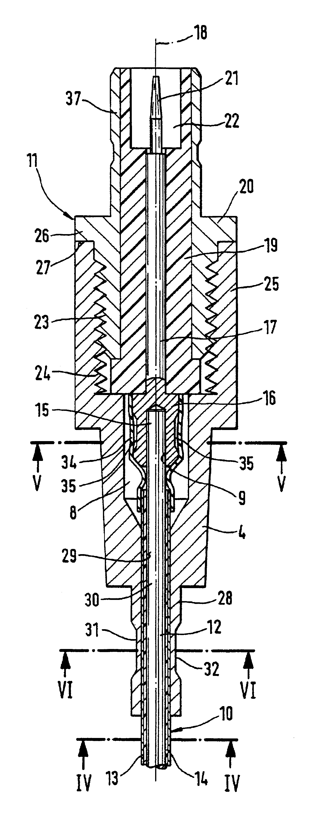
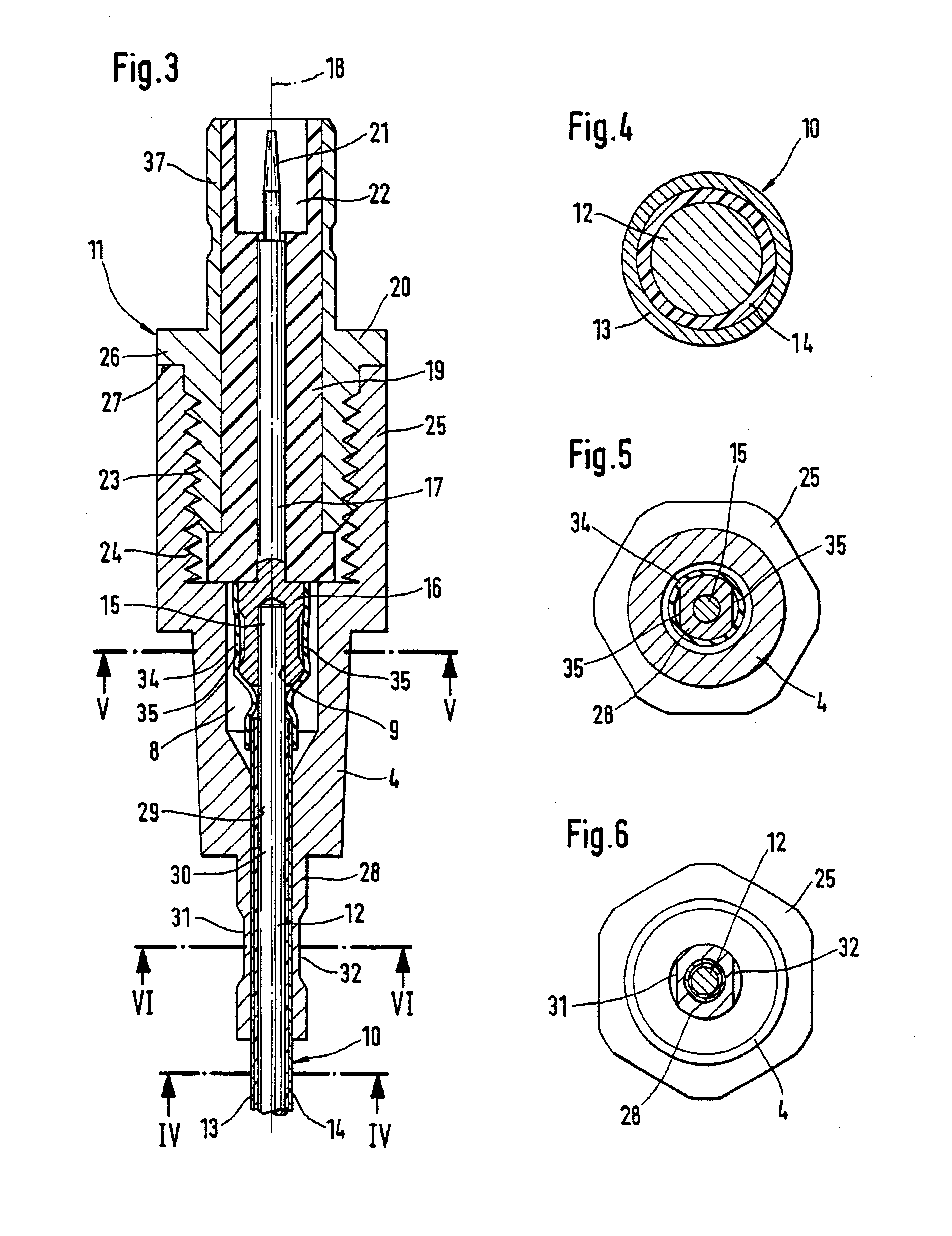
[0010]An embodiment of the present invention with one pole formed by the electrically conductive steel core and the second pole formed of a conductive jacket layer, which may be applied to an insulator layer enclosing the jacket surface of the steel core in a closed manner also offers the possibility of manufacturing and handling such a combination needle in a simple manner.
[0012]Further advantageous embodiments of the present invention are disclosed herein, and these embodiments have especially the advantage of offering the possibility of using at least partly commercially available plug-type connections and of manufacturing the contacting connections between the conductive parts of the steel mandrel and the plug part in a purely mechanical manner, i.e., without soldering or welding, in a reliable manner and also with the necessary strength.

Problems solved by technology

Even though an anesthetist can read based on the length scale provided on the jacket surface of the plastic cannula how deep the cannula has penetrated into the skin, the anesthetist cannot determine from this how far the tip of the cannula is located in the vasomotor nerve sheath, because the distance between the vasomotor sheath and the skin surface or the pricking site differs from one patient to the next.
However, this plug socket has only a single-pole design, i.e., only one pole can be connected to a power source at the steel mandrel.
From this arises the drawback that larger parts of the body are always affected by the electric effect of the electrostimulation.

Method used


Image

  • Combination needle for peripheral nerve block
  • Combination needle for peripheral nerve block
  • Combination needle for peripheral nerve block

Examples


Embodiment Construction

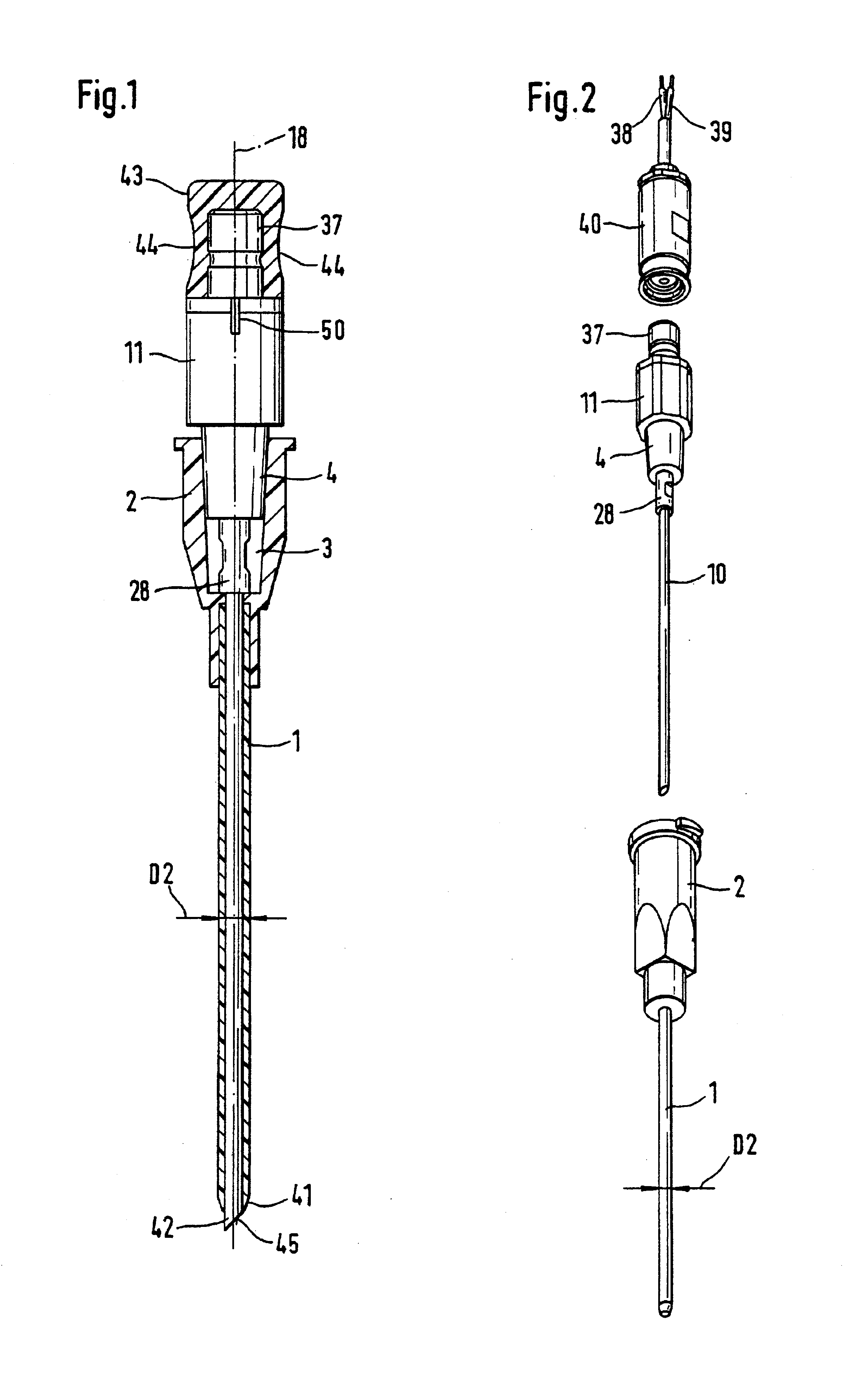
[0022]Referring to the drawings in particular, the combination needle for peripheral nerve block shown in the drawings comprises a plastic cannula 1 and a cylindrical, solid steel mandrel 10. The plastic cannula 1 has a diameter D2 of about 0.8 mm to 1.3 mm, while the diameter D1 of the steel mandrel 10, coordinated with the internal diameter of the plastic cannula 1, may be about 0.6 mm to 1 mm.

[0023]The plastic cannula 1 is provided with a handle 2, which likewise consists of plastic and has a rear-side open cavity 3. This cavity 3 has a conical shape, so that it can fittingly accommodate a so-called Luer's cone 4, which is part of a grip part 11 of the steel mandrel 10. The plastic cannula 1 and its handle 2 are firmly connected to one another in the usual manner.

[0024]The steel mandrel 10 comprises a solid steel core 12, which forms one pole or one electrode in an electrically conductive manner during the electrostimulation. The steel mandrel 10 has a two-pole design due to the ...


PUM


Abstract

The combination needle is intended for peripheral nerve block. It comprises a plastic cannula (1) and an essentially cylindrical, solid steel mandrel (10), which is provided with a pricking tip, which is free from a cutting edge, and with a grip part (11), which has an electric plug contact (21) for the connection of an electrostimulator. The steel mandrel (10) can be introduced into the cannula (1) such that its pricking tip (42) protrudes from the front end of the cannula or is at least flush with same. It shall be achieved with the present invention that the two [“bei der die beiden” in German original should read “die beiden”—Tr.Ed.] electrodes necessary for the electrostimulation are located at a very short distance from one another and the electric effects of the stimulation is [sic—Tr.Ed.] limited to the body area where the stimulation shall take place. The steel mandrel (10) therefore has a two-pole design and is provided with a two-pole electric plug contact means (21, 37).

Description

FIELD OF THE INVENTION[0001]The present invention pertains to a combination needle for peripheral nerve block, comprising a plastic cannula and an essentially cylindrical, solid steel mandrel, which is provided with a pricking tip without a cutting edge and with a grip part, which has an electric plug contact for the connection of an electrostimulator, wherein the steel mandrel can be introduced into the cannula such that its pricking tip protrudes from the front end of the cannula or is at least flush with same.BACKGROUND OF THE INVENTION[0002]A combination needle of this type is known from, e.g., DE 35 08 013 C2. It is used for anesthesia and analgesia of the arm, block of the branchial plexus in the axillary region being preferably performed.[0003]The prior-art combination needle is characterized by special designs of the pricking tip of the steel mandrel comprising a solid bar, which designs are suitable for piercing the nerve sheath consisting of solid tissue, also called neuri...

Claims


Application Information

Patent Timeline
IPC IPC(8): A61B17/34A61N1/05
CPCA61B17/3401A61N1/0551
Inventor KREBS, PETER
Owner KREBS PETER
Learn More