
Method and system for three-dimensional modeling of object fields

a three-dimensional modeling and object field technology, applied in the field of three-dimensional modeling of object fields, can solve the problems of inability of dental practitioners inability to make dental impressions, and inability to achieve the effect of combining (or “stitching”) adjoining parts accurately and low image definition

Inactive Publication Date: 2005-08-02
ATLANTIS COMPONENTS
View PDF10 Cites 51 Cited by
  • Summary
  • Abstract
  • Description
  • Claims
  • Application Information

AI Technical Summary

Benefits of technology

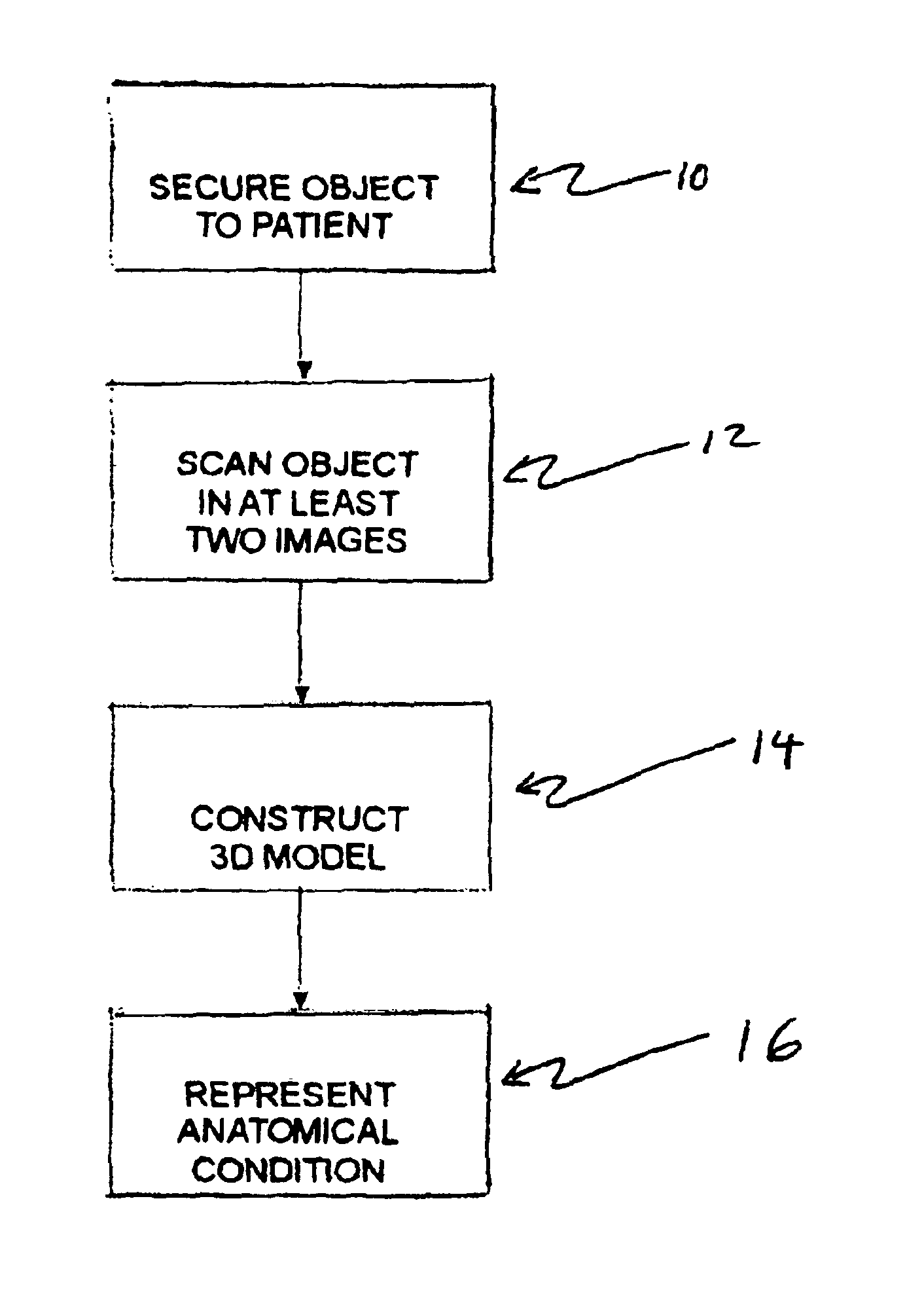
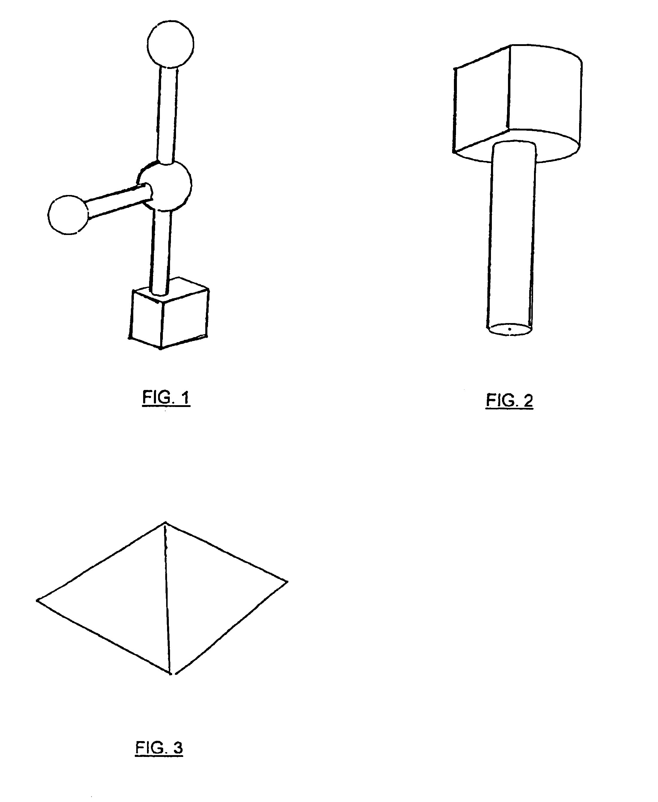
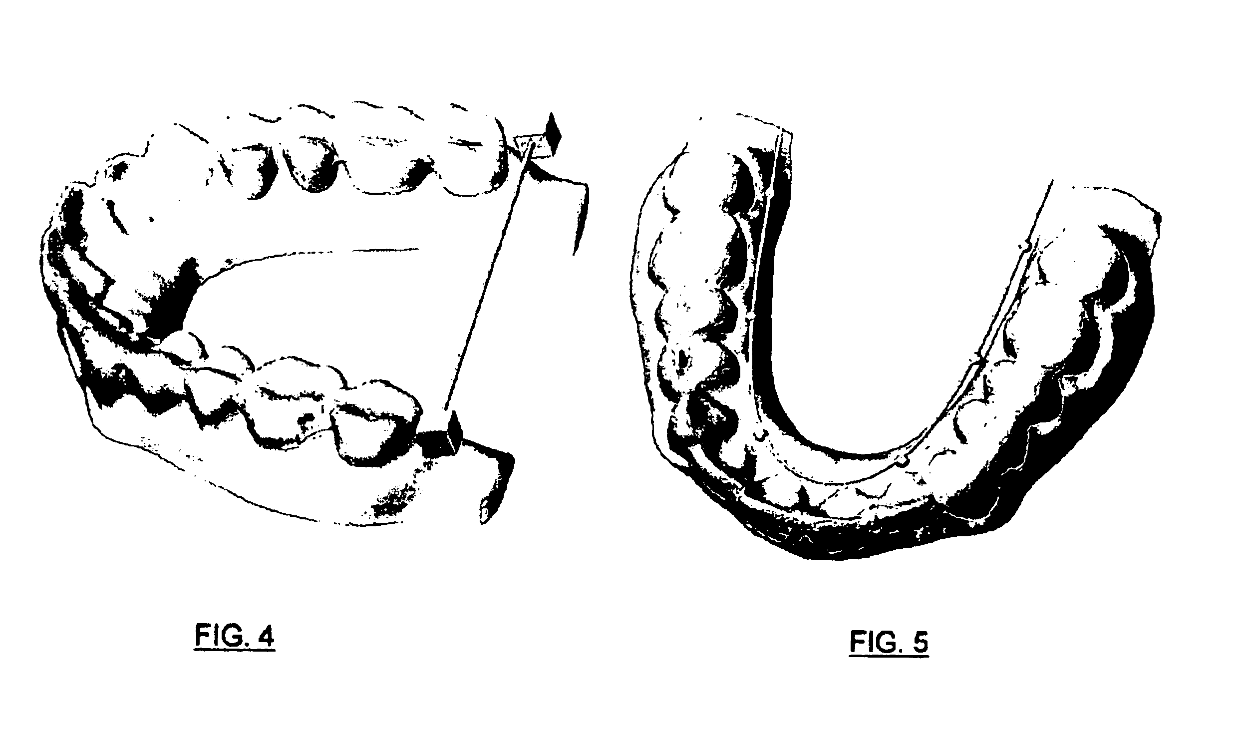
[0009]The present invention is a three-dimensional-based modeling method designed for dentistry and related medical applications. One aspect of the invention dispenses with the need for a specific camera and instead enables the use of any data capture means that produces a point cloud representing the three dimensional surface. Such data capture means may for example be a hand-held or frame-fixed three-dimensional laser scanner, an ordinary digital camera, or any other imaging means that is practically suited to the particular medical application. Another aspect of the invention is the use of three-dimensional recognition objects, to assist photogrammetry software to locate automatically, and to determine accurately the position and orientation of objects within the image field. Yet another aspect of the invention is the positioning of recognition objects having well-defined topography within those areas in the image field that have low image definition, and particularly in such of these areas that appear in overlapping portions of at least two images, to provide the photogrammetry software with position, angulation, and orientation information sufficient to enable highly accurate combining (or “stitching”) of adjoining and overlapping images.

Problems solved by technology

In actual practice the conventional procedure described above is fraught with numerous difficulties and shortcomings.
It has proven impossible for dental practitioners to make dental impressions, and thus models, that are consistently free of dimensional and positional errors; so rigorous are the geometrical requirements involved in such applications that even a sub-millimeter dimensioning error, or a 1 or 2 degree orientation error, will result in prosthetic placements that give rise to unacceptable stresses and conditions.
However the particular demands for great accuracy, and the physical strictures of imaging the human body, have thus far resulted in the absence, in the field of dentistry, of acceptable three-dimensional imaging techniques.
A particular problem is the necessity, for the accurate reconstruction, in the form of a virtual model, of an imaged scene, that the scene be imaged from at least two positions, thereby providing the geometric data required for the application of triangulation methods by the software.
While the methods disclosed in the Carlsson et al. and van Nefteric et al. patents constitute significant advances, these methods still exhibit several important disadvantages and shortcomings that render them impractical for most implant dentistry practitioners.
Both of said methods require the use of highly specialized and accordingly expensive camera equipment, and both require that such camera equipment be precisely aligned, to capture a plurality of images from precisely known relative lens positions.
Functionally, both methods are inadequate to image accurately a wide field of view, particularly a wide field of view comprising areas characterized by very low feature definition, a condition typical of the edentulous (tooth-free) jaw and thus quite common in implant dentistry practice.

Method used


Image

  • Method and system for three-dimensional modeling of object fields
  • Method and system for three-dimensional modeling of object fields
  • Method and system for three-dimensional modeling of object fields

Examples


Embodiment Construction

[0018]The present invention is a method and system for creating virtual three-dimensional models of a scanned field of view, using three-dimensional recognition objects as reference points in the “stitching” of overlapping captured images, and, additionally, positioning such recognition objects in areas of the field of view that are characterized by low feature definition in order to enhance the accuracy of the three-dimensional modeling of such areas.

[0019]The invention is particularly suitable and intended for medical and dental applications, and it is particularly suited for use in the field of implant dentistry and related applications. Dental implants are used to support the restoration of missing teeth. Implant fixtures are surgically implanted by a dentist. These dental implants typically will be “restored” with abutments and crowns; that is, following successful implantation of implant fixtures into the jaw of the patient, complementary components including abutments and cro...


PUM


Abstract

A method and system for creating three-dimensional models of implant-bearing dental arches, and other anatomical fields of view, employs three-dimensional scanning means to capture images of an anatomical field of view wherein there have been positioned (and preferably affixed to an anatomical feature) one or more three-dimensional recognition objects having a known geometry, such as a pyramid or a linked grouping of spheres. Image processing software is employed to locate and orient said recognition objects as reference data for stitching multiple images and thereby reconstructing the scanned field of view. Recognition objects placed in areas of low feature definition enhance the accuracy of three-dimensional modeling of such areas.

Description

FIELD OF THE INVENTION[0001]The invention is a method and system for determining the relative location of objects and features in a plurality of overlapping scanned images. The invention is particularly directed to medical and dental applications including those that require surgical and prosthetic devices to be designed and manufactured to precise dimensions dictated by the anatomy of individual patients.BACKGROUND OF THE INVENTION[0002]Many surgical procedures concern the temporary or permanent insertion, into the soft or bony tissue of a patient, of prosthetic and other artificial devices that are required to fit the anatomy of the patient to a very high degree of precision and accuracy. One such application concerns implant dentistry, in the course of which one or more (usually metallic) implant anchors are surgically placed within the jawbone of a patient, to receive and support prosthetic components designed to simulate and replace one or more natural teeth lost by the patient...

Claims


Application Information

Patent Timeline
IPC IPC(8): G06K9/00G06K9/36G06T17/00A61C1/08A61C9/00G06T7/00G06V10/24
CPCA61C1/084G06K9/32G06T17/00A61C9/0046G06T7/0024G06K2209/05G06T2207/30004G06T2207/30204G06T7/30G06V10/24G06V2201/03
Inventor SCHARLACK, RONALD S.GRANT, BETHANY F.
Owner ATLANTIS COMPONENTS
Learn More