
Method and apparatus for improving material properties

a technology of metallic materials and properties, applied in the direction of nuclear engineering, energy-based chemical/physical/physico-chemical processes, railway components, etc., can solve the problems of time-consuming and complex painting and drying steps, unsatisfactory methods, and difficulty in applying tape to complex components in itself, so as to achieve less time-consuming

Inactive Publication Date: 2005-08-02
ROLLS ROYCE PLC
View PDF44 Cites 33 Cited by
  • Summary
  • Abstract
  • Description
  • Claims
  • Application Information

AI Technical Summary

Benefits of technology

[0008]It is therefore desirable to provide an improved and more efficient method and apparatus that addresses the above problems and replaces the complex painting and drying steps with a less time consuming process, and / or offers improvements to such a method and apparatus generally.
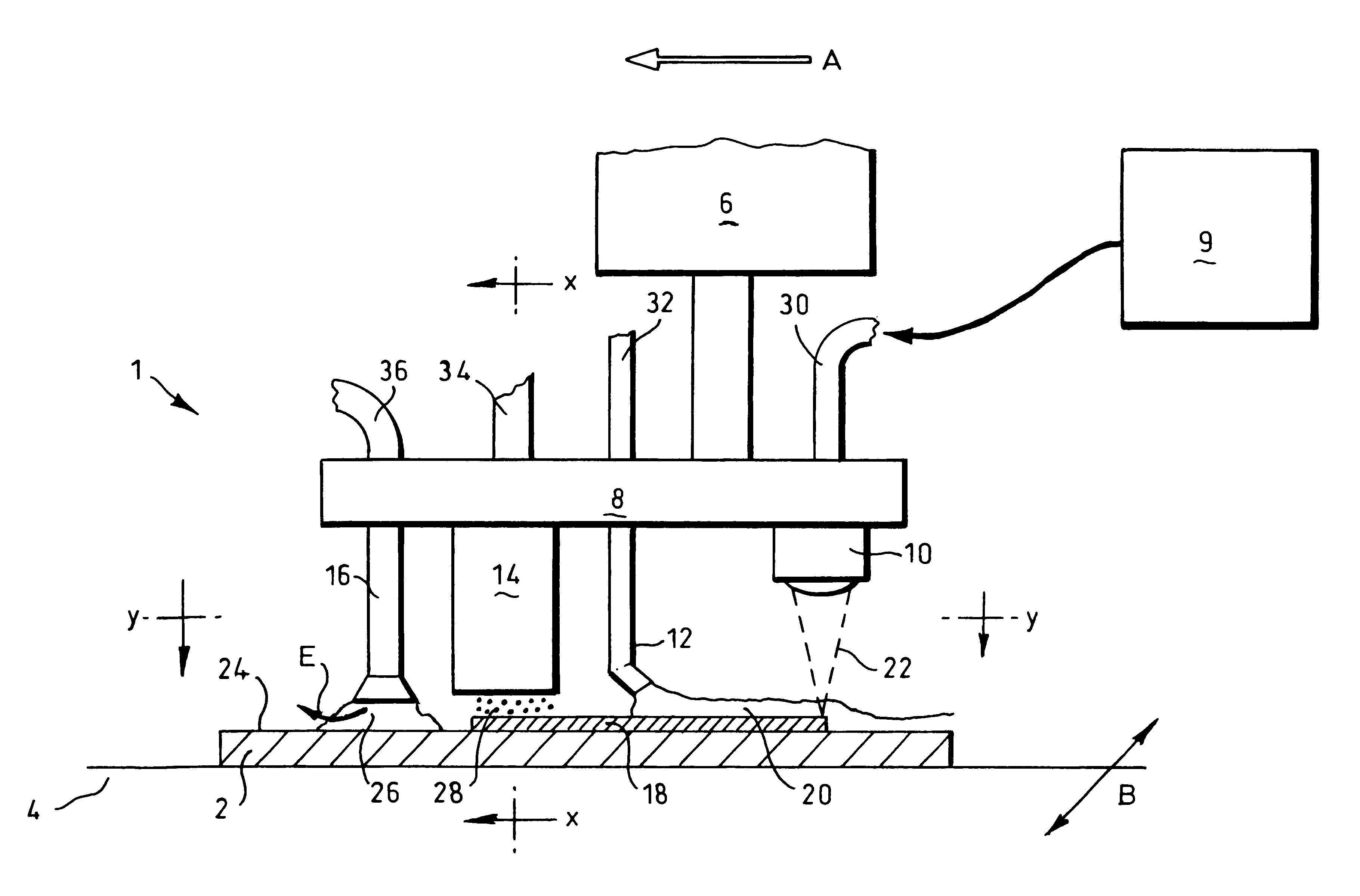
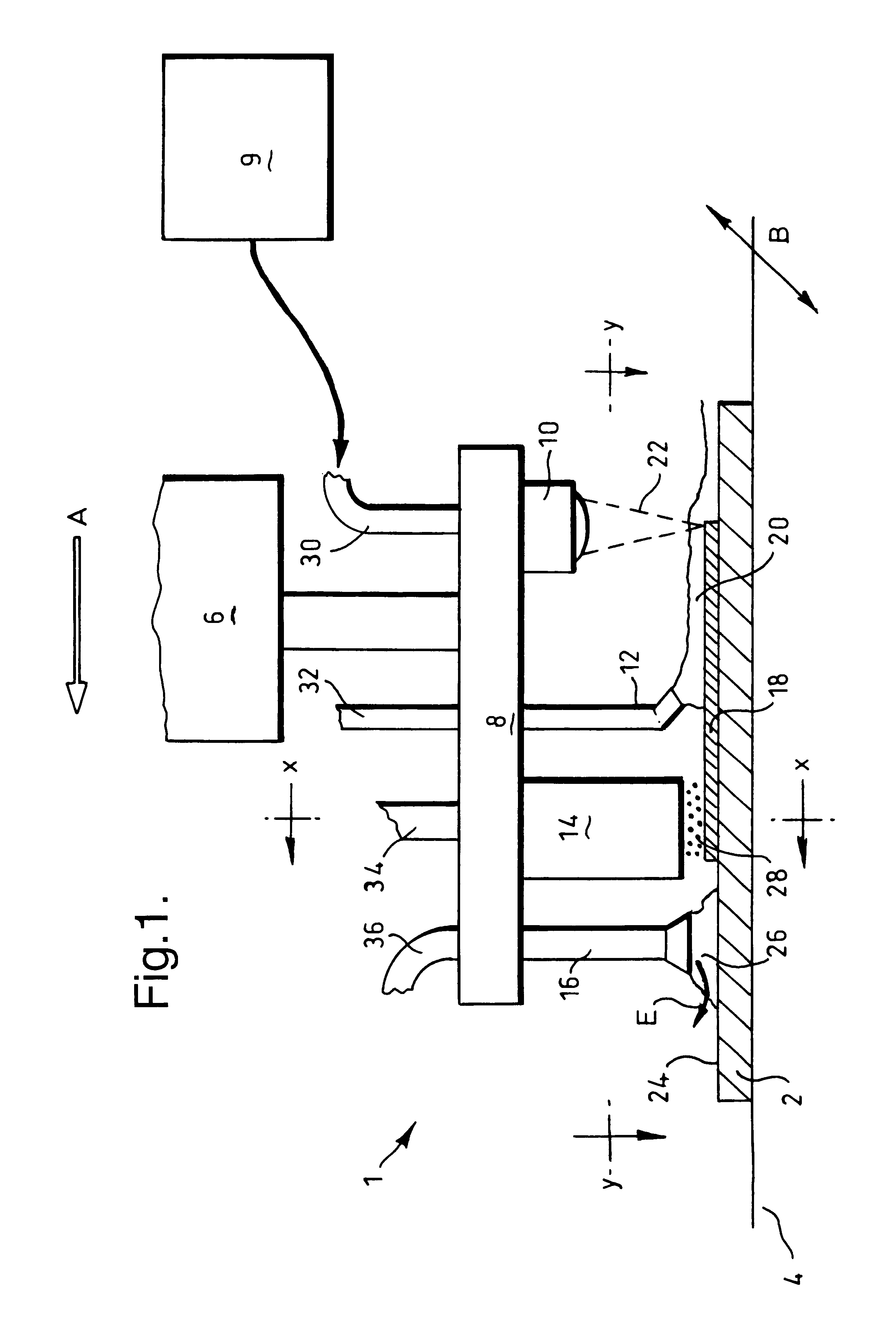
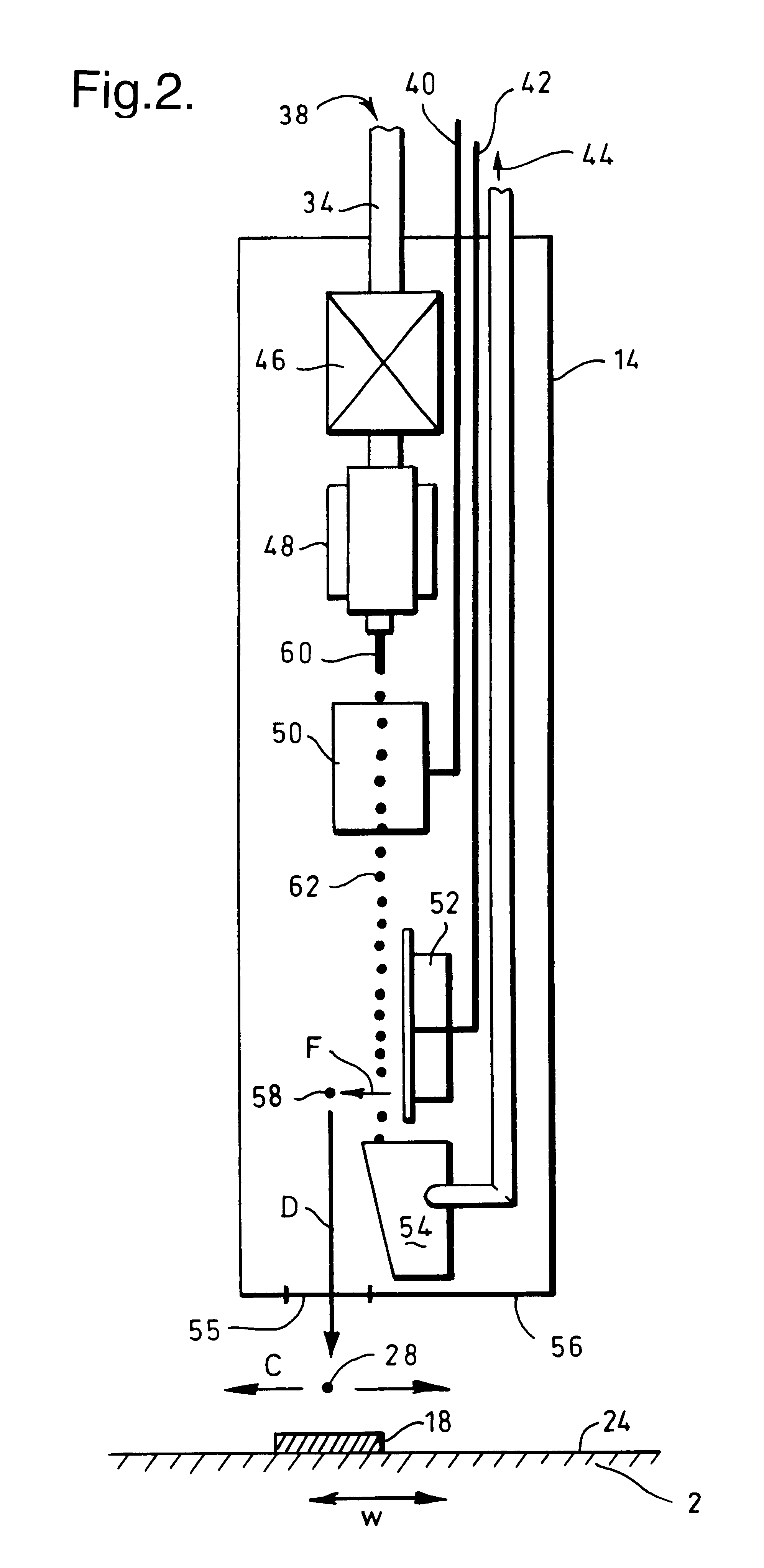
[0009]According to a first aspect of the present invention there is provided a method improving the properties of a material of a workpiece by laser shock peening in which an overlay which is opaque to a laser beam, and an overlay which is translucent to said laser beam, are applied to a surface of a workpiece, the translucent overlay being applied on top of and over the opaque overlay, a laser beam is then directed at the said surface to which the overlays have been applied to vaporise the opaque overlay and laser shock peen the surface of the workpiece producing a region of compressive residual stress in said surface; wherein the opaque overlay, translucent overlay and the laser shock peening are applied concurrently, in a single operation, as the surface of the workpiece is traversed so that as each point on the surface to be treated is traversed the opaque overlay, translucent overlay, and laser shock peening are applied sequentially to that point.
[0010]Applying the opaque overlay, translucent overlay and the laser shock peening concurrently is more efficient than the conventional methods and does not require the workpiece to be removed and installed in different machines. Furthermore the method is also quicker than carrying out these operations separately.
[0011]According to a second aspect of the present invention there is provided a method of improving the properties of a material of a workpiece by laser shock peening in which an overlay which is opaque to a laser beam, and an overlay which is translucent to said laser beam, are applied to a surface of a workpiece and a laser beam is then directed at the said surface to which the overlays have been applied to vaporise the opaque overlay and laser shock peen the surface of the workpiece producing a region of compressive residual stress in said surface; wherein the at least one of the overlays is applied by printing an ink layer on the surface of the workpiece.
[0012]Using an ink layer as the opaque overlay speeds up the process since an ink dries faster than the conventionally used paints. In addition printing the opaque overlay in the form of an ink layer is also more controllable than the conventional painting methods.
[0016]Such an apparatus is more integrated than the conventional apparatus and by utilising a common tool head to mount and move the means for applying the opaque and translucent overlays and the means for directing the laser is overall simpler and more efficient than mounting such means separately.

Problems solved by technology

The painting and drying steps are time consuming and complex.
Whilst eliminating the time consuming painting and drying steps this method is not ideal.
Applying tape to a complex component may in itself be difficult and time consuming and the cost of a the tape may be significant.
Furthermore this method described does not address the problem of having to remove the workpiece from the laser shock peening machine in order to reapply the opaque overlay (either paint or tape) during repetition of the laser shock peening process.

Method used


Image

  • Method and apparatus for improving material properties
  • Method and apparatus for improving material properties
  • Method and apparatus for improving material properties

Examples


Embodiment Construction

[0027]Laser shock peening is a known process for improving the properties of a workpiece material. The process involves directing and scanning a laser beam over a surface of a workpiece; an opaque overlay and a translucent overlay having previously been applied to the surface of the workpiece that is to be treated. The laser beam passes through the translucent overlay. The opaque overlay however absorbs the energy of the laser beam and rapidly vaporises and expands. The translucent overlay confines the vaporisation of the opaque overlay thereby generating a shock wave which acts upon the surface material of the workpiece. This shock wave provides a local compressive force on the surface material which advantageously generates a deep region of residual compressive stress in the surface material of the workpiece. In the interests of brevity it will be assumed that the skilled man in the art is familiar with the conventional details of this technique and of the conventional apparatus u...


PUM

PropertyMeasurementUnit
Translucencyaaaaaaaaaa
Opacityaaaaaaaaaa
Residual stressaaaaaaaaaa

Abstract

A method and apparatus for improving the properties of a material of a workpiece by laser shock peening in which an overlay which is opaque to a laser beam, and an overlay which is translucent to said laser beam, are applied to a surface of a workpiece. The translucent overlay being applied on top of and over the opaque overlay. A laser beam is then directed at the said surface to which the overlays have been applied to vaporize the opaque overlay and laser shock peen the surface of the workpiece to produce a region of compressive residual stress in said surface. The overlays and the laser beam being applied concurrently, in a single operation, as the surface of the workpiece is traversed so that as each point on the surface to be treated is traversed the opaque overlay, translucent overlay, and laser shock peening are applied sequentially to that point. The opaque overlay is preferably an ink layer which is applied by printing on the surface. The apparatus, which in particular is arranged for carrying out this method, comprises the means for applying the overlays and for directing the laser beam at the surface all mounted upon a common tool head.

Description

THE FIELD OF THE INVENTION[0001]The present invention relates to methods and apparatus for improving the properties of a metallic material, and in particular to improvements to laser shock peening which imparts compressive residual stresses into the material to improve its material properties.BACKGROUND OF THE INVENTION[0002]Laser shock peening or laser shock processing, as it is also referred to, is a process for improving the properties of a metallic material from which a workpiece is fabricated. As with any peening process, for example shot peening, it does this by producing a region of deep compressive residual stresses in the material at the surface of a workpiece. The region of such compressive residual stresses in the surface of a workpiece provides a protection layer which beneficially increases the surface material's resistance to surface-related failures such as fatigue, fretting and stress corrosion cracking. A difference, and advantage of, laser shock peening is that thi...

Claims


Application Information

Patent Timeline
IPC IPC(8): B23K26/18C21D10/00C21D7/00C21D7/06
CPCB23K26/18C21D10/005B23K26/009C21D7/06
Inventor ANDERSON, RAYMOND I
Owner ROLLS ROYCE PLC
Learn More