
Gas concentration detecting apparatus

a technology of gas concentration and detecting apparatus, which is applied in the direction of liquid/fluent solid measurement, electrochemical variables of materials, instruments, etc., can solve the problems of rough resolution of nox concentration and inability to meet the desired concentration detection accuracy, so as to enhance the precision of detecting gas concentration and reduce the differences among the sensing characteristics of sensors

Active Publication Date: 2005-07-26
DENSO CORP
View PDF7 Cites 19 Cited by
  • Summary
  • Abstract
  • Description
  • Claims
  • Application Information

AI Technical Summary

Benefits of technology

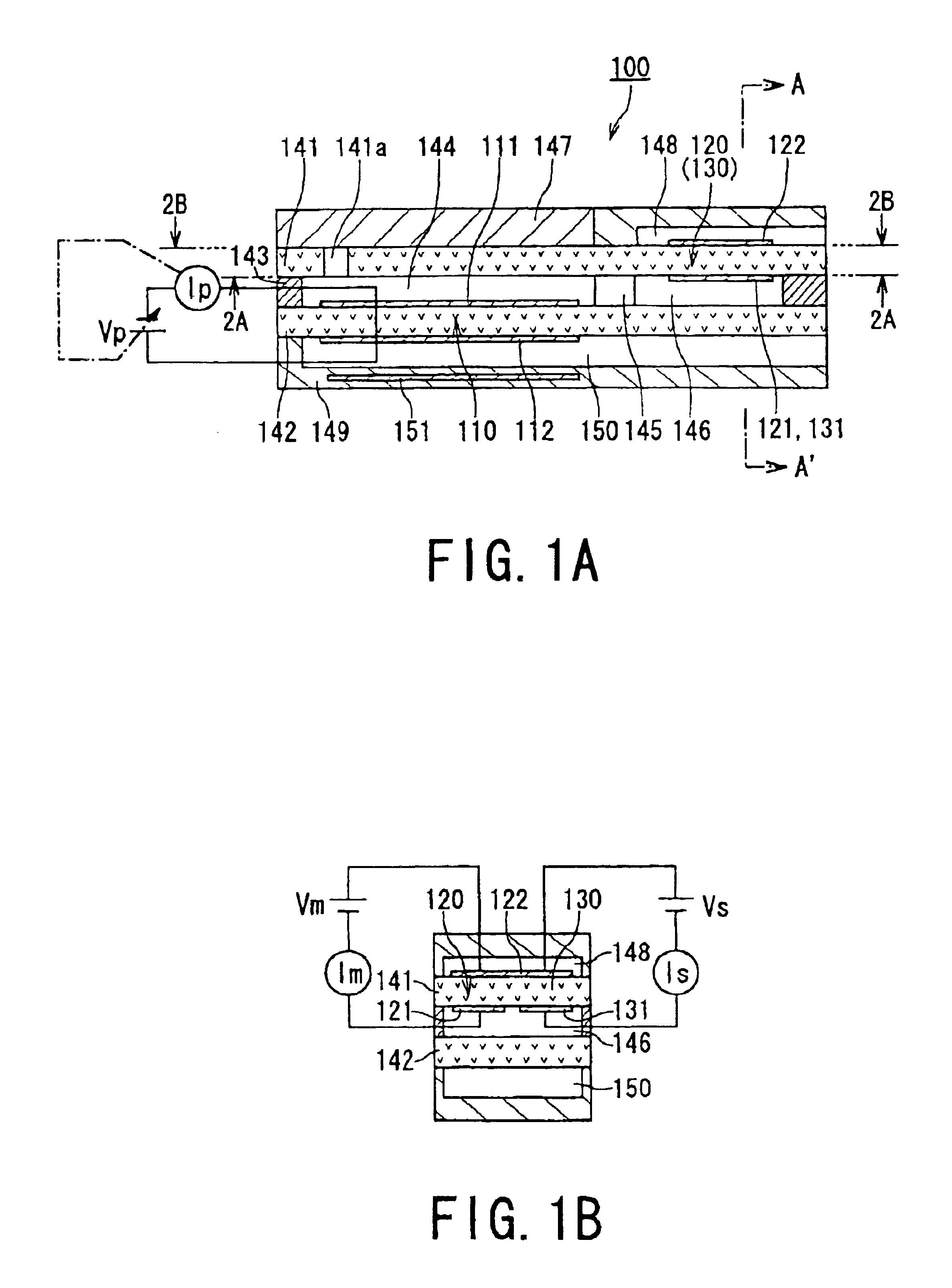
[0010]In the gas concentration calculator, a plurality of concentration calculating means are provided, so that their concentration detecting ranges can be set differently in a scale from each other. Resolution for the concentration in each of the concentration calculating means can therefore be set individually. Compared to the concentration calculating means having a larger concentration detecting range, the concentration calculating means having a larger concentration detecting range shows a smaller concentration resolution. In consequence, precision for detecting the specific gas component can be raised. In any application, it is therefore possible to meet a desired gas detecting precision.
[0013]The concentration of the specific gas component is detected from a gas in the second cell, the gas having passed along the first cell. The gas still contains residual oxygen, with the result that the residual oxygen caused an offset error in the second sell current. It is possible to detect this offset error by measuring the third cell current. Thus subtracting the third cell current from the second cell current provides a second cell current of which offset error is removed, improving detection accuracy of the concentration of the specific gas component. It is therefore desired to perform such subtraction to detect the concentration of the specific gas component.
[0015]In this configuration, before the A / D conversion, the differential amplifying circuit (that is, hardware circuit) operates to remove, through its subtraction, an offset error component (which corresponds to the third cell current signal) from the second cell current signal. Hence the gain given to the differential amplifying circuit can be raised, which widens the dynamic range of a signal to be inputted to the A / D converter. This leads to an increase in the resolution of the A / D conversion, compared to a configuration where the second cell current signal containing an offset error component is directly subjected to the A / D conversion (conventionally, the offset error component obliged the A / D converter to have a wider input range, thus lowering the resolution).
[0017]According to this configuration, at least in concentration calculating means of which concentration detecting range is small, the foregoing subtraction can be carried out before the A / D conversion. Therefore, the advantage that the dynamic range of a signal to be inputted the A / D converter is raised can be provided in the similar way to the foregoing. This advantage can accelerate the foregoing improvement in precision of detecting the concentration, when such subtraction configuration is applied to the concentration calculating means of which concentration detecting range is small.
[0019]In this configuration, the foregoing subtraction can also be carried out before the A / D conversion. Therefore, the advantage that the dynamic range of a signal to be inputted the A / D converter is raised can be provided.
[0023]Accordingly, the foregoing configurations for the correction allow actual characteristics of the sensor to be reflected to its operations for calculating the concentrations based of the measured various current signals, thereby enhancing precision in detecting gas concentrations. Still, the foregoing sensitivity correction and oxygen-concentration-dependency correction can be performed every sensor, so that differences among the sensing characteristics of the sensors can be lessened or eliminated.

Problems solved by technology

However, as described above, in cases where the NOx concentration should be given to plural applications and the regulatory compliance forces the concentration detecting range to be extended, resolution for the NOx concentration becomes rough, because a microcomputer or other processing apparatuses are usually limited in a processing facility.
In contrast, for applications such as engine control, such a limited processing capability may cause a problem that a desired concentration detecting accuracy cannot be met.

Method used


Image

  • Gas concentration detecting apparatus
  • Gas concentration detecting apparatus
  • Gas concentration detecting apparatus

Examples


Embodiment Construction

[0038]An embodiment of the present invention will now be described in conjunction with the appended drawings.

[0039]An embodiment of the present invention will now be described in connection with the appended drawings. In this embodiment, a gas concentration detecting apparatus applied to for instance the automobile engine is provided. The apparatus employs a limiting current type of gas concentration sensor to detect not only an oxygen concentration of an exhaust gas serving as a gas to be detected but also a NOx concentration as a concentration of a particular gas component included in the exhaust gas.

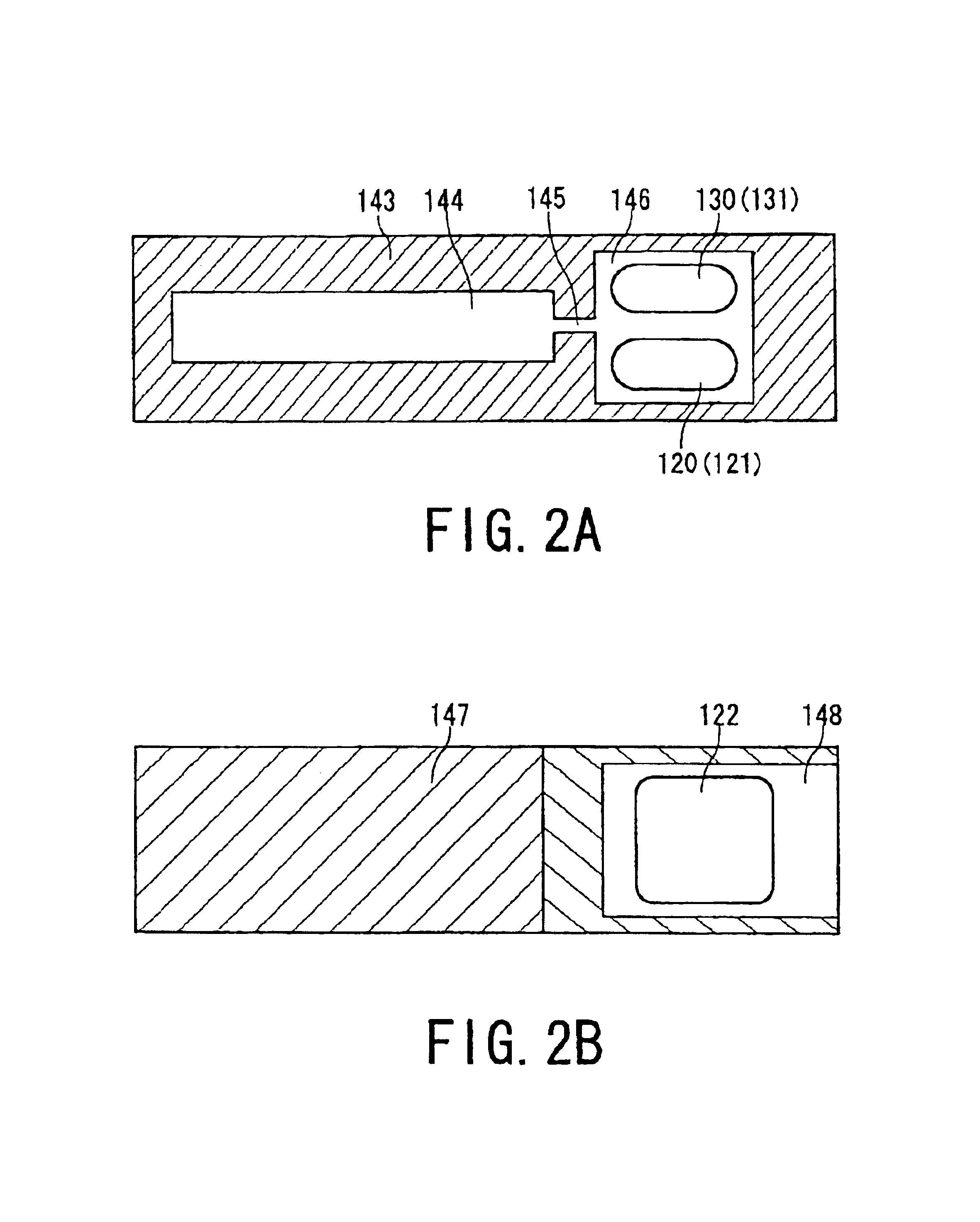
[0040]First of all, with reference to FIGS. 1A and 1B, the configuration of a gas concentration sensor 100 will now be described. The gas concentration sensor 100 shown in FIGS. 1A and 1B is structured to have three cells consisting of “a pump cell” serving as “a first cell,”“a sensor cell” serving as a “second cell,” and “a monitor cell” serving as “a third cell,” which is therefore ...


PUM

PropertyMeasurementUnit
currentaaaaaaaaaa
currentaaaaaaaaaa
currentaaaaaaaaaa

Abstract

A gas concentration detecting apparatus comprises a gas concentration sensor and a gas concentration calculator. The sensor has first to third cells. A gas to be detected is introduced in a chamber and the first cell is responsible for discharging and changing oxygen from and into the chamber. The second cell detects a concentration of a specific gas component of the gas that has passed along the first cell. The third cell detects a concentration of residual oxygen in the gas that remains after discharge of the oxygen through the first cell. The calculator takes in a current acquired from the second cell measured with a voltage applied thereto and calculates the specific gas component concentration based on the current. The calculator includes plural concentration calculating means whose concentration detecting ranges are mutually different in a scale. The specific gas component concentration is calculated every concentration calculating means.

Description

BACKGROUND OF THE INVENTION[0001]1. The Field of the Invention[0002]The present invention relates to an apparatus for detecting a concentration of a gas[0003]2. Related Art[0004]A gas concentration detecting apparatus has many types depending on applications. One type, as disclosed by Japanese Patent Laid-open (KOKAI) publication No. 2002-20285, is an apparatus that employs a limiting current type of gas concentration sensor in order to, for example, detect NOx (nitrogen oxide) included in an exhaust gas discharged from an automobile engine. In this apparatus, the gas concentration sensor is structured, as an example, to have three cells consisting of a pump cell, a sensor cell, and a monitor cell. The pump cell is responsible for discharging and drawing oxygen in an exhaust gas taken into a chamber, during which time the pump cell detects an oxygen concentration in the exhaust gas. The sensor cell detects a NOx concentration (i.e., a concentration of a particular gas component) fro...

Claims


Application Information

Patent Timeline
Patent Type & Authority Patents(United States)
IPC IPC(8): G01N27/417G01N27/419G01N27/26G01N27/416
CPCG01N27/419
Inventor KAWASE, TOMOOKUROKAWA, EIICHI
Owner DENSO CORP
Learn More