
Load/unload method and a magnetic disk drive using the method

Inactive Publication Date: 2005-07-19
NEOMAGIC +1
View PDF14 Cites 21 Cited by
  • Summary
  • Abstract
  • Description
  • Claims
  • Application Information

AI Technical Summary

Benefits of technology

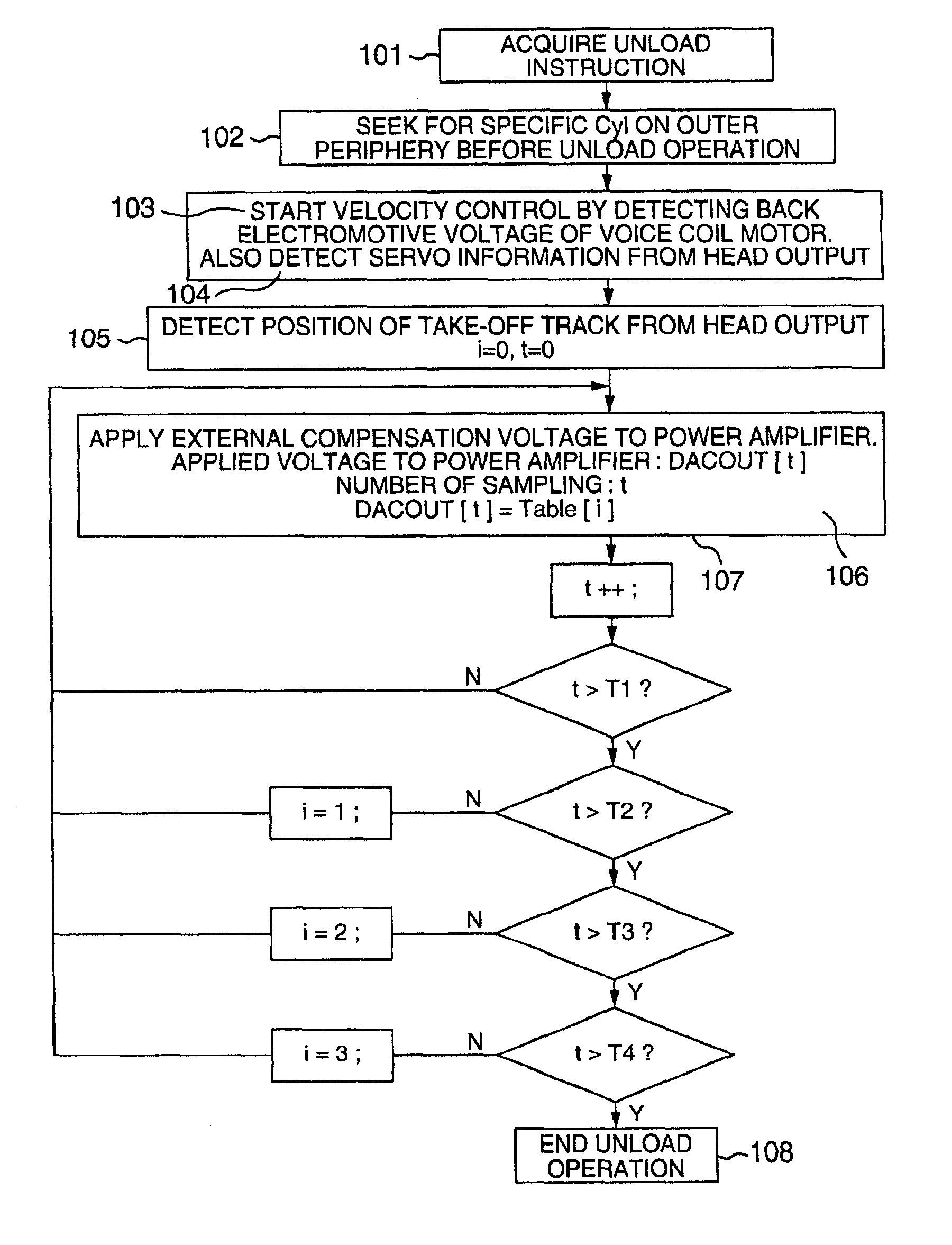
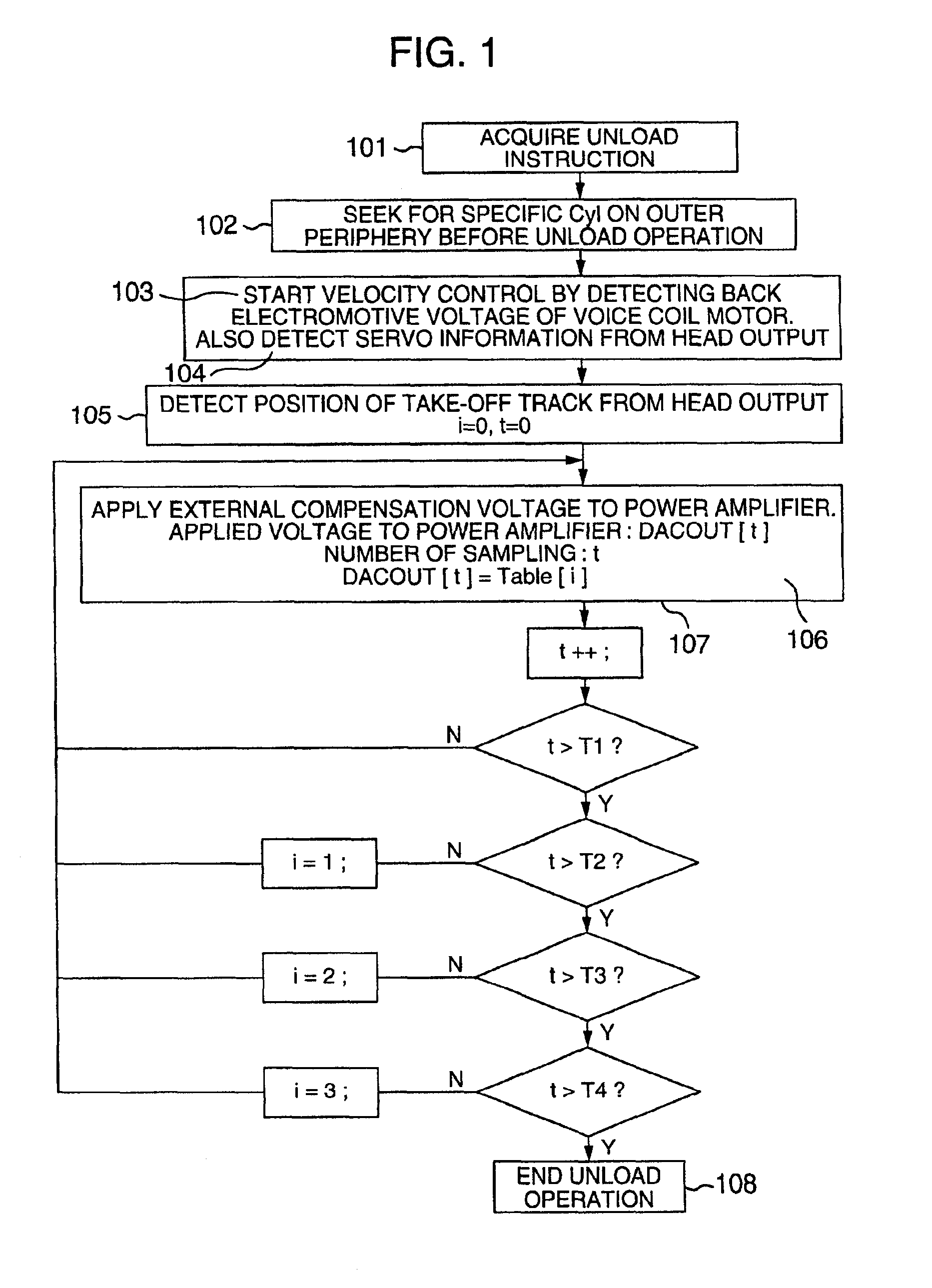
[0015]The present inventors have taken note of the fact that the magnetic disk drive controls the velocity by feedback through a VCM (voice coil motor) and a control circuit thereof, and has come to hit an idea that the unload operation, if started at a predetermined reference position outer on the magnetic disk media, can subsequently be accurately controlled. In other words, the position at which the slider is unloaded is detected from the information recorded on the magnetic disk media, whereby the subsequent unload operation is controlled accurately.
[0016]An object of the present invention is to provide a technique for carrying out the stable load / unload operation for a magnetic disk drive having a load / unload mechanism, in which an actuator for moving the slider having the magnetic head mounted thereon is prevented from slowing down, temporarily stopping or otherwise changing the speed during the load / unload operation.
[0017]Another object of the invention is to provide a technique for controlling the load / unload operation for the magnetic head, in which the speed at which the slider support members including the suspension run into the ramp is set to a necessary and sufficient level lower than in the prior art thereby to reduce the wear caused by the friction between the ramp and the slider support members such as a suspension tab while at the same time suppressing the generation of dust for an improved reliability.
[0018]Still another object of the invention is to provide a technique for controlling the load / unload operation for the magnetic disk drive and the magnetic head, in which the speed of the slider unloaded and moved following the ramp is constantly maintained at a steady level thereby making it possible to avoid the collision between the slider separated from the magnetic disk media and the magnetic disk media under the shock of separation.
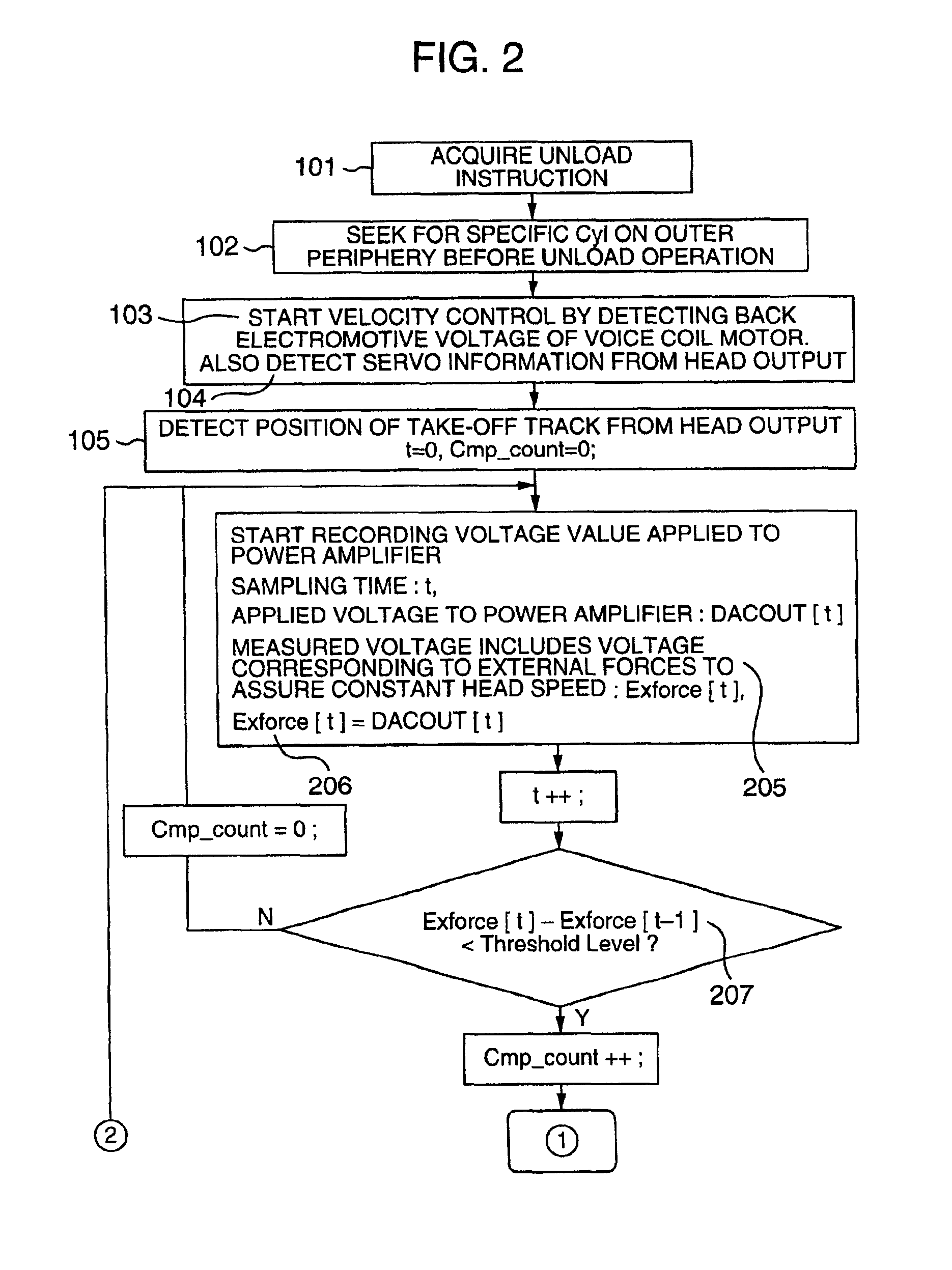
[0019]Yet another object of the invention is to provide a technique for controlling the load / unload operation for the magnetic disk drive and the magnetic head, in which the servo information and other control signals are written in the outer periphery of the magnetic disk media so that the position at which the slider lands on or takes off from the magnetic disk media in the load / unload operation can be recognized accurately by the magnetic disk drive based on the signal from the magnetic head, thereby making it possible to compensate for the values of the voltage or the current supplied to the power amplifier for driving the VCM, measurements and records of other parameters and the recorded values corresponding to the external forces including the friction exerted between the ramp and the slider support members and the suction exerted between the slider and the magnetic disk media.

Problems solved by technology

In the case where the information is not exchanged, a slider having the magnetic head mounted thereon is undesirably kept on the magnetic disk media at the risk of the slider and the magnetic disk media coming into collision with each other under an external shock that may deteriorate shock resistance performance.
On the other hand, the method of keeping the slider in a predetermined area of the magnetic disk media when the media stop rotating (contact start-stop (CSS)) is also undesirable as an adhesion would develop between the slider having the magnetic head mounted thereon and a specific magnetic disk medium.
As a result, the inconveniences such as the collision between the slider and the magnetic disk media have often occurred.
In the case where the slider is moved to the ramp with a simple constant value, therefore, the slider would slow down or temporarily stop thereby making it difficult to withdraw it over the ramp at a steady rate.
In the prior art, the slider movement is controlled only roughly in the load / unload operation, thereby leading to such inconveniences as the collision between the slider and the magnetic disk media, the friction between or the wear of the ramp member and the slider support members, the generation of dust, etc.
Also, after the slider support members run into the ramp, the slider separated from the magnetic disk media at an insufficiently high position of the ramp collides with the magnetic disk media under a separation shock.
Further, the accurate velocity control operation has not been performed in spite of the need thereof for withdrawing the slider at a steady rate in the unload operation.
Thus, the magnetic head sometimes misses the servo information in an area on the magnetic disk media where no servo information is written, with the result that the slider support members having the magnetic head mounted thereon and the ramp often collide with each other at a speed higher than the target speed.

Method used


Image

  • Load/unload method and a magnetic disk drive using the method
  • Load/unload method and a magnetic disk drive using the method
  • Load/unload method and a magnetic disk drive using the method

Examples


Embodiment Construction

[0029]Embodiments of the present invention will be described below with reference to the drawings.

[0030]The process for fabricating a magnetic disk drive according to this invention is schematically shown in FIG. 8.

[0031]The servo information are written in magnetic disk media 602 by a servo track writer unit 701 before being built in the spindle motor of the magnetic disk drive. The servo track writer unit 701 stacks a plurality of magnetic disk media through spacers on a core 703 mounted on the spindle portion 705 and can write the servo information collectively on these magnetic disk media in the block.

[0032]In the method of writing the servo information using the magnetic head of the magnetic disk drive after the magnetic disk media are built in the magnetic disk drive, assume that the magnetic disk drive includes a load / unload mechanism. A part of the load / unload mechanism including a ramp 608 (FIG. 7), for example, interferes with the slider or other support members having the...


PUM


Abstract

To control load / unload operation of a slider with magnetic head mounted thereon, by which the speed can always be controlled stably while avoiding the slowdown or temporary stop of an actuator during load / unload operation, a magnetic disk drive is configured using magnetic disk media with the servo information written therein beforehand up to the track located at a position corresponding to the landing zone for the load operation of the magnetic head (slider). The speed of the magnetic head (slider) withdrawn to the ramp is controlled at the unload operation. In the stage of initialization for controlling the speed of the load / unload operation, various parameters are recorded and updated to apply a voltage to power amplifier for compensating for the external forces caused by the friction mainly exerted between ramp and slider support members, with reference to the take-off track or the landing track specified in the landing zone.

Description

BACKGROUND OF THE INVENTION[0001]The present invention relates to a load / unload mechanism for a magnetic head, or in particular to the operation of controlling the load / unload mechanism smoothly by acquiring information from magnetic disk media.[0002]A magnetic disk drive is a peripheral device in which a magnetic head writes (records) or reads (reproduces) information into or from at least a rotating magnetic disk medium for exchanging the information with a host system. In the case where the information is not exchanged, a slider having the magnetic head mounted thereon is undesirably kept on the magnetic disk media at the risk of the slider and the magnetic disk media coming into collision with each other under an external shock that may deteriorate shock resistance performance. On the other hand, the method of keeping the slider in a predetermined area of the magnetic disk media when the media stop rotating (contact start-stop (CSS)) is also undesirable as an adhesion would deve...

Claims


Application Information

Patent Timeline
IPC IPC(8): G11B21/21G11B5/54G11B21/12G11B5/60
CPCG11B5/54G11B5/6005G11B21/12G11B21/21
Inventor TOMINAGA, HIDEFUMIARAI, TSUYOSHIHORIGUCHI, TAKAOKIKUTA, TOSHIYUKIFUJII, YOSHIKATSU
Owner NEOMAGIC
Learn More