Method for compacting powder materials into articles and a mold for implementing the method

Inactive Publication Date: 2005-07-19
TOMSKIJ POLITEKHNICHESKIJ UNIVT
View PDF3 Cites 4 Cited by
  • Summary
  • Abstract
  • Description
  • Claims
  • Application Information

AI Technical Summary

Benefits of technology

[0054]An object of the present invention is to provide a method for compacting powder materials into articles, in which the powder material density is more evenly distributed throughout the article volume, and which allowing easier removal of liquid and / or process lubricant and entrapped air from the volume of the compacted articles, extend permissible range of compaction pressures, wider assortment and improved quality of powder articles of all complexity groups, elimination of destructive impact of forces of wall friction against surfaces of the closed cavity of the shaping member when the article is removed therefrom, reduced costs of production, operation and service of the molds, less stringent requirements to strength and elastic characteristics of the mold material.
[0055]A further object of the present invention is to provide a mold for compacting powder materials into articles, the design of which offers a more uniform distribution of powder density throughout the article volume, this, in turn, allowing easier removal of liquid and / or process lubricant and entrapped air from the volume of the compacted articles, extended permissible range of compaction pressures, wider assortment and improved quality of powder articles of all complexity groups, elimination of destructive impact of forces of wall friction against surfaces of the closed cavity of the shaping member when the article is removed therefrom, reduced costs of production, operation and service of the molds, less stringent requirements to strength and elastic characteristics of the mold material.
[0073]Advantageously, the mold further comprises means for preventing an off-axis displacement of the one-piece or composite shaping members, said means being a structural element selected from the group consisting of a shroud, a fixture, a pivot of the common axis of mutual movement of the shaping members, a spline engagement of the one-piece or composite members with one another, a bayonet engagement of the one-piece or composite shaping members, an elastic enclosure.
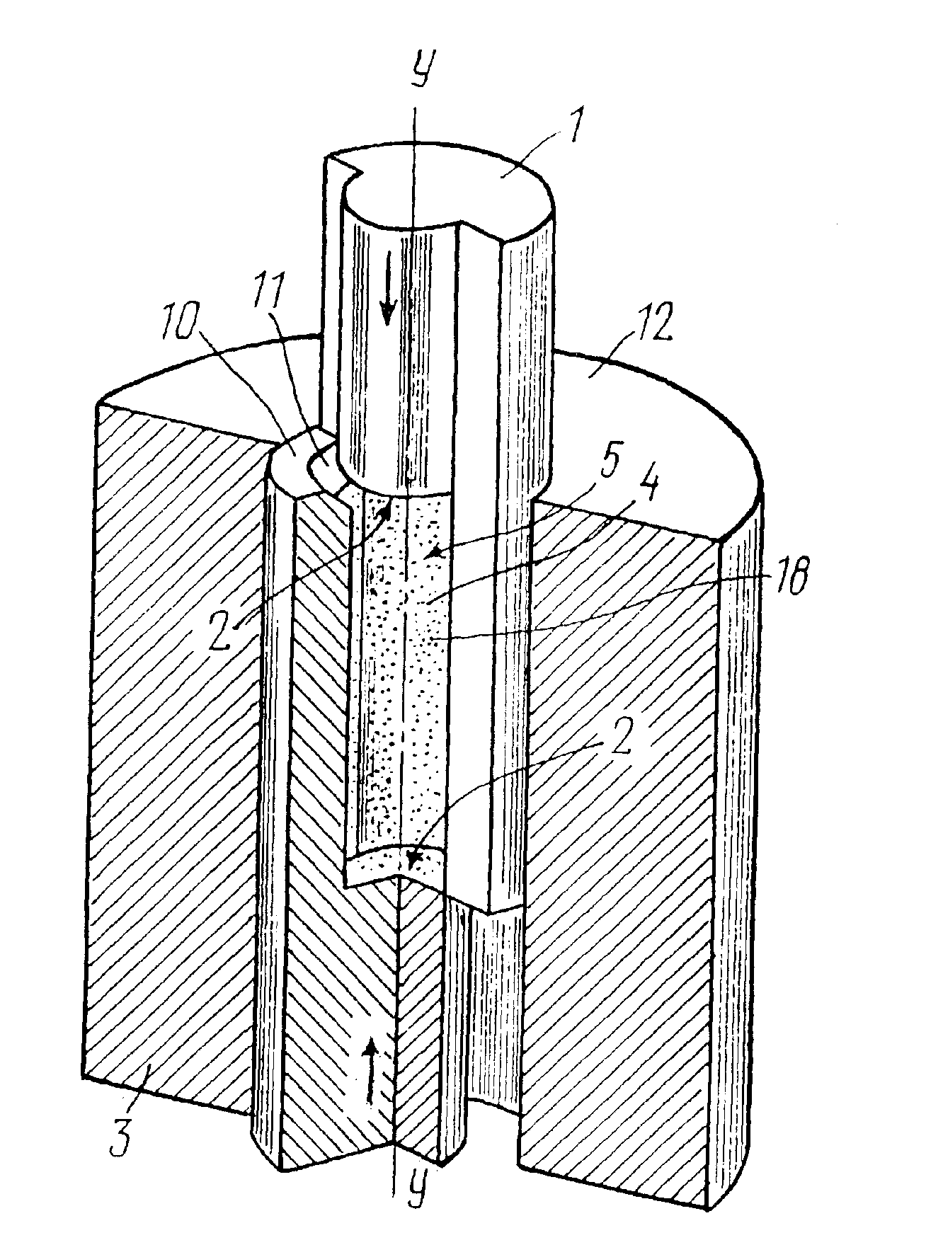
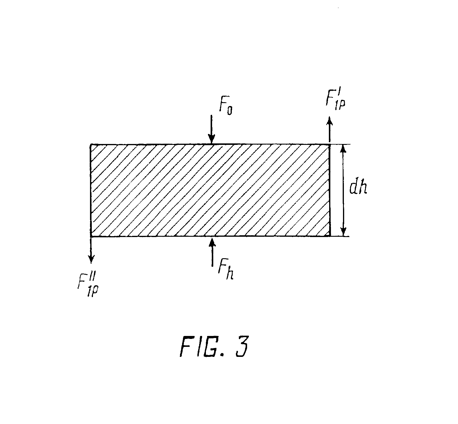
[0095]The presence of the active shaping surface and a part of the passive shaping surface on each of the shaping members of the mold provides the condition of creating oppositely directed wall friction forces and appearance of the compaction pressure of constant value that is transferred to all layers of the powder article and provides the same ratio of their compaction.
[0096]The shaping members of the present mold have the section receiving the pressing force that substantially exceeds the dimension of the hydraulic section of the compacted article, this allowing the compaction pressure to be considerably increased beyond the limits of the maximum permissible mechanical stress value for the material of mold members. This extends the range of the compaction pressure and alleviates requirements to the material quality of the molds for compacting powder materials.

Problems solved by technology

The basic problem with the prior art method is that in all compacting routes the average density distribution of the powder article through its cross-section normal to the pressing axis, along the article height and throughout the volume has an explicitly nonuniform character with the layers of the same density being bent in the direction of the pressing punch movement (Shtern M. B., Serdyuk G. G., Maximenko L. A., Trukhan Y. V., Shulyakov Y. M. Phenomenological Theories of Powder Compacting, Kiev, Naukova dumka, 1982).
When compacting articles of irregular shape with a developed surface, split dies are used in order to eliminate destructive impact of elastic aftereffect (Klyachko L. I., Umansky A. M., Bobrov V. N. Equipment and Accessories for Forming Powder Materials, Moscow, Metallurgy, 1986), this increases the number of die components and complicates the process of die fabrication and operation, but the problems of obtaining an acceptable uniform density of pressed articles along the height still remain.
The method of compacting sleeves with counter movement of the matrix and the insertion rod has a significant drawback.
When forming a sleeve-shaped article, it is impossible to provide uniform distribution of density along the height of the article as areas of its side surfaces (internal and external) cannot be equal.
In compacting hard-to-form powders this causes stratification of long-length articles, leads to nonuniform shrinkage and inadmissible changes in the shape in further sintering.
It should be noted that the constraints currently placed on purity of materials in powder technology, the quest for reduction in costs and simpler preparation operations prohibit the use of lubricants in manufacture of critical parts.
Furthermore, reduction of wall friction parameters by process lubricants will prevent meeting the uniform density requirement.
This makes requirements to the mold material quality more stringent, reduces service life of the mold and substantially restricts the permissible range of compaction pressures, especially for the articles having a small section in the direction of the pressing axis.
The presence of closed passive shaping surfaces on the mold members, that are hard to reach directly and the quality of which must meet stringent requirements, makes their processing in the manufacturing process and maintenance in operation of the mold more difficult.
When long-length articles of plastic powders that are prone to entrapping air, or powders with a high content of liquid or process lubricant are fabricated in the prior art mold, their removal from the closed volume of the matrix cavity in the compacting process is problematic.
However, rigid connection of the matrix and one of the punches substantially hampers or even prevents removal of the compacted article.

Method used


Image

  • Method for compacting powder materials into articles and a mold for implementing the method
  • Method for compacting powder materials into articles and a mold for implementing the method
  • Method for compacting powder materials into articles and a mold for implementing the method

Examples


example

[0152]Using a method for compacting in accordance with the invention without lubricants, fluidizing agents and ultrasonic oscillation, articles of the seventh complexity group were fabricated of a raw plasmachemical finely dispersed powder of technical ceramic with the composition ZrO2-3 mole % Y2O3. None of the articles was defective.

[0153]The rated density differential along the height of the article fabricated by a prior art single-action static compacting was about 4%.

[0154]In the articles fabricated by the present method, the rated density differential was about 0.5% which correlates well with the differential value of 0.7-0.3% calculated from expression (13) depending on a floating or counter movement route of the insertion member. The nonzero density differential is explained by the fact that the condition of equality of parts of the passive shaping surface cannot be met in full measure.


PUM

PropertyMeasurementUnit
Fractionaaaaaaaaaa
Volumeaaaaaaaaaa
Shapeaaaaaaaaaa

Abstract

A method for compacting powder materials into articles comprises placing a powder material in a shaping cavity of a mold, the cavity being defined by active and passive shaping surfaces of one-piece or composite shaping members of the mold; mutually moving the shaping members of the mold along a pressing axis, with the pressing force transferred from the shaping members of the mold to the powder material through the active shaping surfaces. Surfaces of the powder article, parallel to the pressing axis, are formed by the passive shaping surfaces of the one-piece or composite shaping members of the mold. According to the invention, surfaces of the powder article, parallel to the pressing axis, are formed using parts of at least one passive shaping surface, located on the one-piece or composite shaping members split along the pressing axis. The shaping members of the mold are moved so that at least one continuous surface of the powder article, parallel to the pressing axis, is formed by the parts of at least one passive shaping surface split along the pressing axis, the parts belonging to different shaping members moving in opposite directions. A mold is also disclosed for implementing the method.

Description

FIELD OF THE INVENTION[0001]The present invention relates to power metallurgy and more particularly to a method for compacting powder materials into articles and a mold for implementing the method, and can find application in various branches of industry.BACKGROUND OF THE INVENTION[0002]A method is known for uniaxial single-action compacting of powder materials in closed molds comprising a matrix with a passive shaping surface that does not transfer the pressing force to the powder being compacted, and punches with shaping surfaces that are capable of transferring the pressing force to the powder being compacted (see e.g. Fedorchenko I. M., Frantzevich I. N., Radomyslensky I. D. et al., Powder Metallurgy. Materials, Processing, Properties, Fields of Application, Kiev, Naukova dumka, 1985). The compacting is accomplished by transferring the pressing force to the powder through the active shaping surface of one of the punches. The prior method permits fabrication of articles of Comple...

Claims


Application Information

Patent Timeline
IPC IPC(8): B22F3/03B30B15/02B22F3/00B22F3/02
CPCB30B15/022B22F3/03B22F7/06
Inventor DVILIS, EDGAR SERGEEVICHKHASANOV, OLEG LEONIDOVICHSOKOLOV, VITALY MIKHAILOVICHPOKHOLKOV, JURY PETROVICH
Owner TOMSKIJ POLITEKHNICHESKIJ UNIVT
Why Eureka
Try Eureka