
System and method for demonstrating and investigating brownian motion effects on a diamagnetically suspended particle

a diamagnetic suspension and motion effect technology, applied in the direction of speed/acceleration/shock measurement, instruments, specific gravity measurement, etc., can solve the problems of inconvenient process control, inconvenient measurement of inability to change the temperature of sample being measured

Inactive Publication Date: 2005-07-19
INTELLECTUAL DISCOVERY INC
View PDF16 Cites 6 Cited by
  • Summary
  • Abstract
  • Description
  • Claims
  • Application Information

AI Technical Summary

Benefits of technology

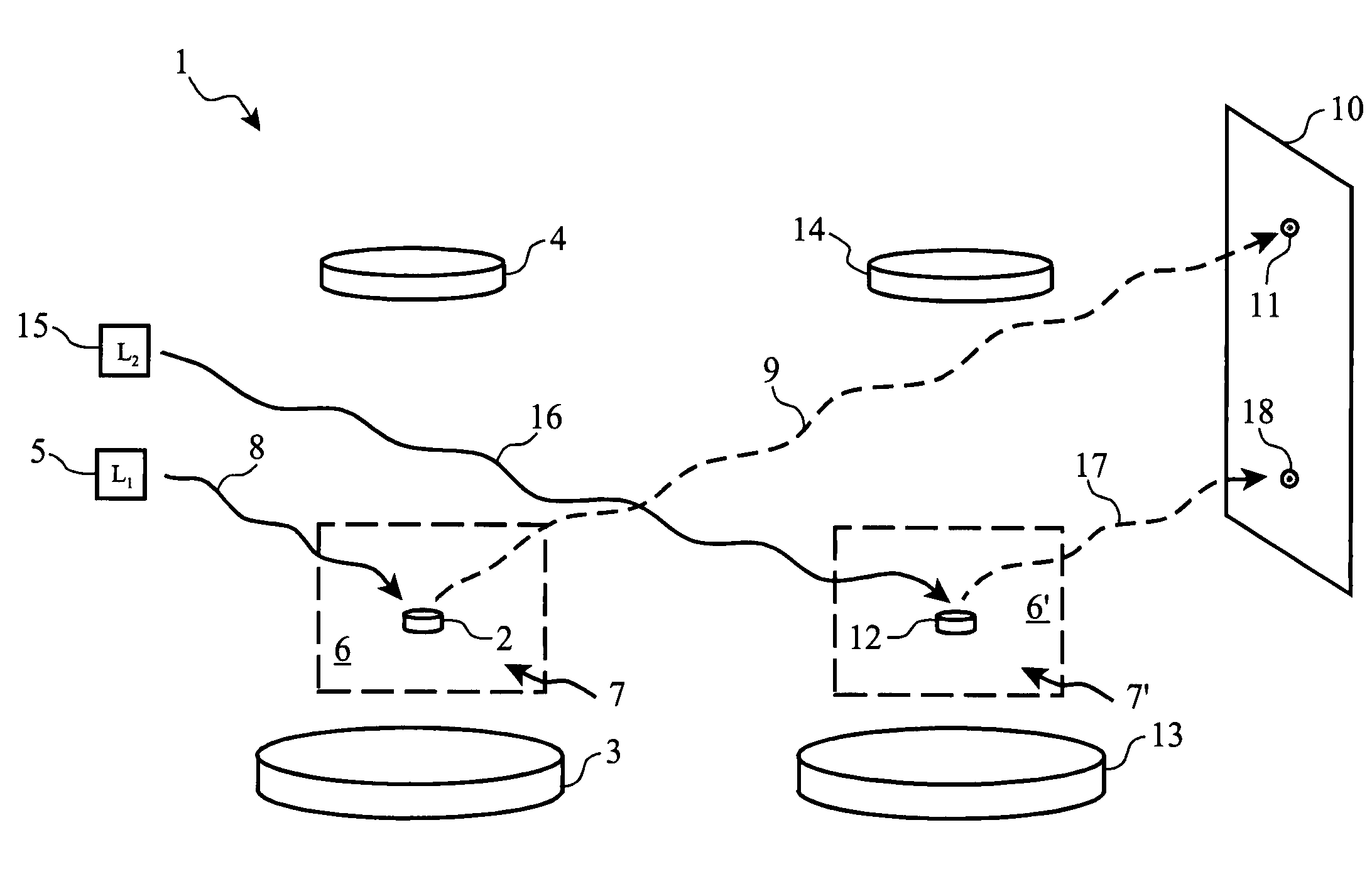
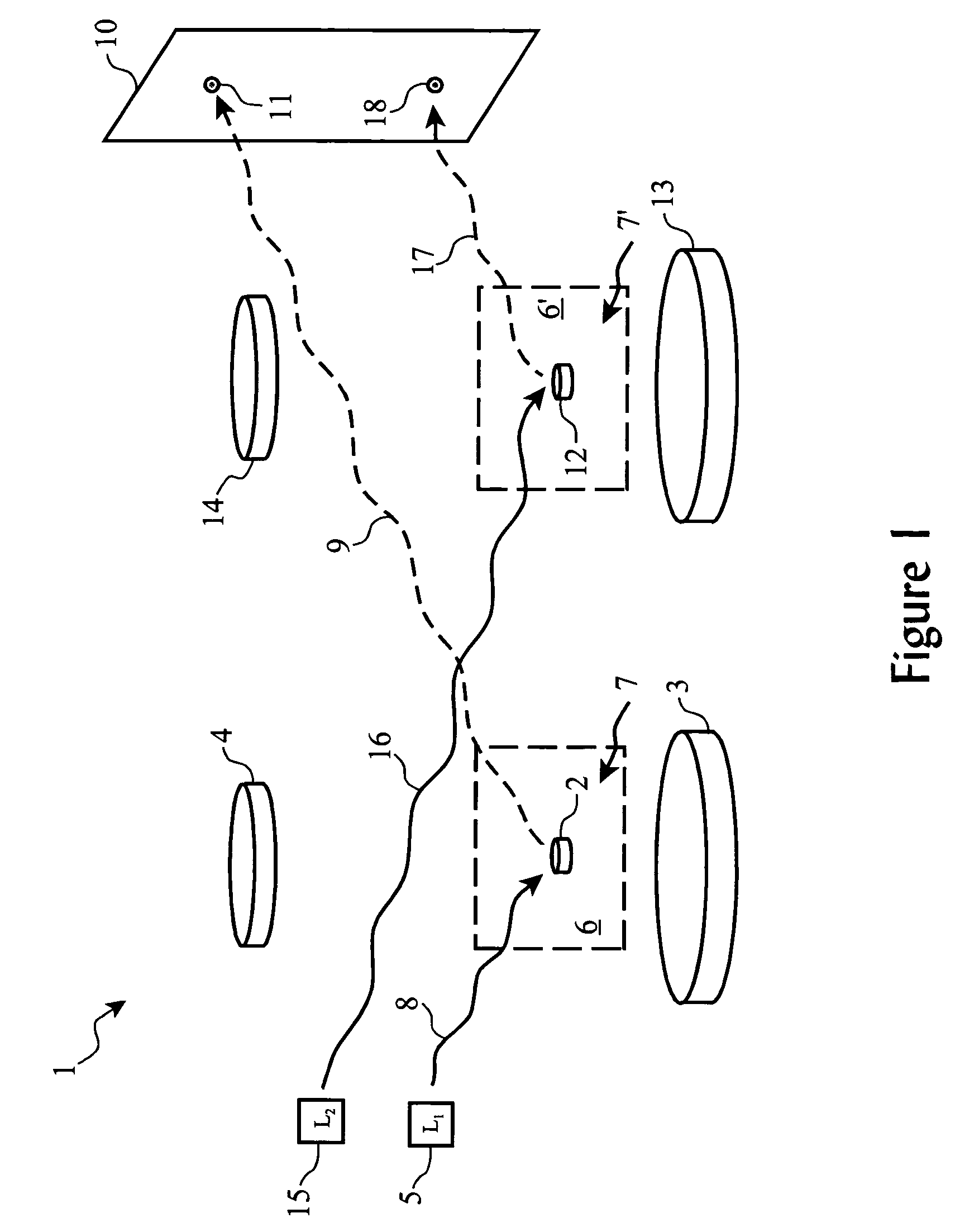
[0024]To further enhance the observation and investigation, a second particle is also diamagnetically suspended by a similar arrangement or device, although it is suspended in a relative vacuum instead of a gas. The second particle is configured at a distance sufficient so as not to magnetically interact with the first suspended mass (or with suitable magnetic shielding between the two).
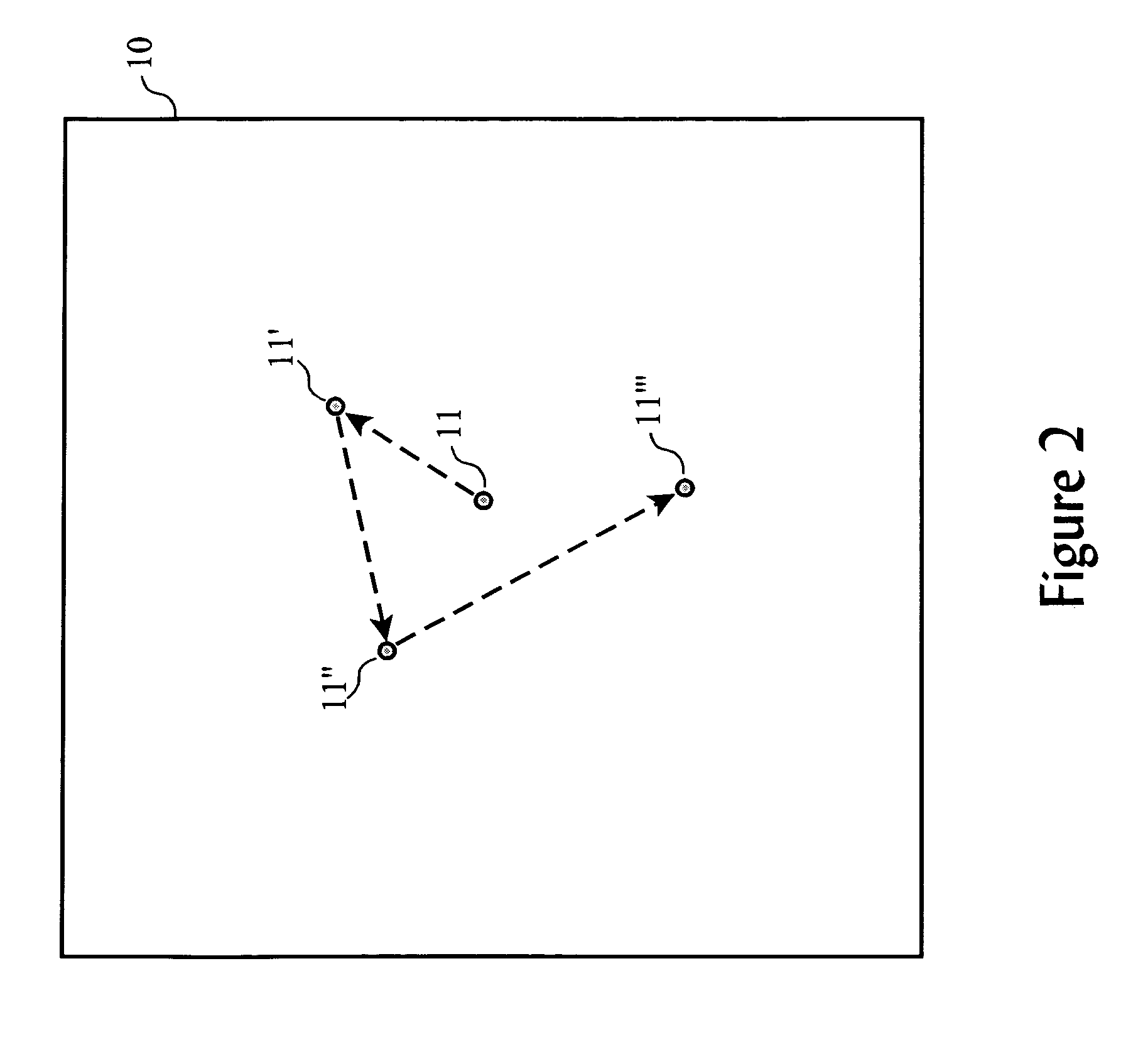
[0026]Thus, by observing both particles' movement simultaneously and over time, a filter can be employed to effectively allow demonstration and investigation of only the Brownian movement of the first particle, thereby yielding a demonstration relative to the temperature of the gas which is insensitive to external mechanical and electromechanical noise.

Problems solved by technology

Both the thermocouple and the expansive metal approaches, however, have the possibility of changing the temperature of the sample being measured, especially for very small samples of gas or liquid.
This disadvantage arises out of the fact that the thermocouple or metal each contains its own amount of thermal energy prior to being immersed in the sample material, and when immersed, adds (or subtracts) thermal energy to (or from) the sample material in order to assume the same temperature of the sample.
Additionally, these methods require a waiting period for the measuring device to equalize with the temperature of the sample, which may not be conducive to processes requiring more rapid temperature measurements for purposes of process control, manufacturing automation, etc.
For extremely low temperatures, these devices and techniques are inadequate.
In such a situation, measuring the temperature of the gas or solid under test or within the reaction poses special problems, as most methods of probing the gas or solid create the potential of changing the temperature, or require structures too small for practical implementation.
This approach, while useful for cantilever magnetometry and Magnetic Resonance Force Microscopy (“MRFM”) experiments, suffers from a number of limitations and disadvantages.
Most notably, it is not operable at sample temperatures above the temperature of sublimation of oxygen, and thus is not useful for a wide range of interesting applications.
Additionally, it is not applicable to scenarios where a thin cantilever device is impractical.

Method used


Image

  • System and method for demonstrating and investigating brownian motion effects on a diamagnetically suspended particle
  • System and method for demonstrating and investigating brownian motion effects on a diamagnetically suspended particle
  • System and method for demonstrating and investigating brownian motion effects on a diamagnetically suspended particle

Examples


Embodiment Construction

[0027]The present invention differs from the proposed approach by Thurber in two major aspects. First, Thurber proposes ignoring effects of Brownian motion on the sample material, suspending the sample mechanically using a thin cantilever, and using paramagnetic properties of a doping agent (e.g. frozen oxygen) to bend the cantilever according to the temperature of the sample. Our method, however, employs the Brownian Motion effects (instead of ignoring them) as the primary temperature measuring mechanism, suspends a particle in the sample using diamagnetics (as opposed to using a mechanical support such as a cantilever), and requires no doping of the sample (e.g. requires no frozen oxygen), and therefore is useful at much higher sample temperatures.

[0028]As Brownian Movement effects are not ignored by our approach, we first present an overview of Brownian motion phenomena.

Brownian Motion Phenomena

[0029]Brownian Motion, also referred to as Brownian Movement, is a well-known physical...


PUM


Abstract

An apparatus for demonstrating, investigating and observing Brownian motion and temperature of a medium, such as gas or liquid, uses a small particle which is diamagnetically suspended in the medium. The tiny magnetized particle having a known mass is levitated using a diamagnetic technique, and the displacement of the particle over time is observable, which can be used to determine a temperature of the medium. Optionally, a second particle is suspended in a vacuum but mechanically connected to the same apparatus as the first enclosure with the first particle, thereby allowing observation and measurement of non-Brownian movement of the structure, and allowing more precise observation of Brownian movement effects on the first suspended particle.

Description

CROSS-REFERENCE TO RELATED APPLICATIONS (CLAIMING BENEFIT UNDER 35 U.S.C. 120)[0001]The present application is a continuation-in-part of U.S. patent application Ser. No. 10 / 455,158, filed on Jun. 5, 2003, now U.S. Pat. No. 6,799,462, and of U.S. patent application Ser. No. 10 / 607,487 filed on Jun. 26, 2003 now U.S. Pat. No. 6,832,518, currently under Notice of Allowability, both by Viktors Berstis, commonly assigned to applicant of the present application.INCORPORATION BY REFERENCE[0002]The related U.S. patent application Ser. Nos. 10 / 455,158 and 10 / 607,487, filed on Jun. 5, 2003, and Jun. 26, 2003, respectively, both by Viktors Berstis, are incorporated by reference in their entireties, including drawings.FEDERALLY SPONSORED RESEARCH AND DEVELOPMENT STATEMENT[0003]This invention was not developed in conjunction with any Federally sponsored contract.MICROFICHE APPENDIX[0004]Not applicable.BACKGROUND OF THE INVENTION[0005]1. Field of the Invention[0006]This invention relates to techn...

Claims


Application Information

Patent Timeline
Patent Type & Authority Patents(United States)
IPC IPC(8): G01V7/02G01V7/00
CPCG01V7/02
Inventor BERSTIS, VIKTORS
Owner INTELLECTUAL DISCOVERY INC
Learn More