
Encoder and decoder for moving picture

a technology which is applied in the field of encoder and decoder for moving pictures, can solve the problems of undesired influence of image quality error on subsequent frames, inability to perform the above-described concealing process, and inability to achieve the effect of reducing the quality of an image caused by the error

Inactive Publication Date: 2005-07-12
FUJITSU LTD
View PDF6 Cites 37 Cited by
  • Summary
  • Abstract
  • Description
  • Claims
  • Application Information

AI Technical Summary

Benefits of technology

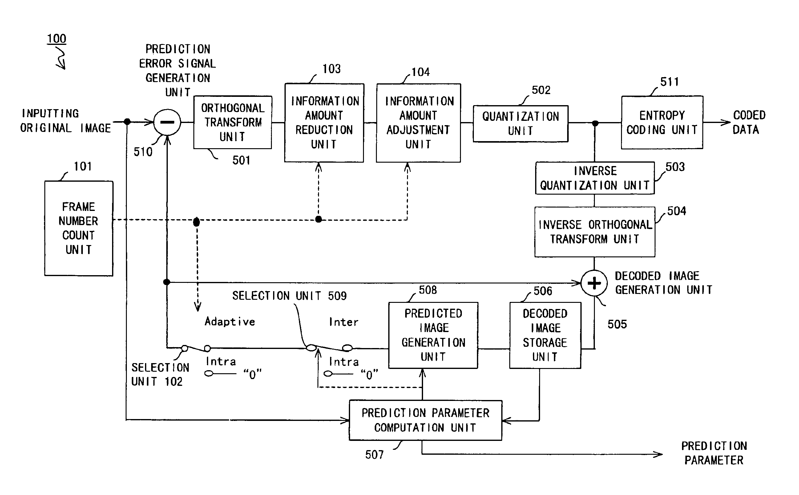
The present invention provides an encoder and decoder capable of quickly obtaining a good image even when there are transmission errors in moving picture data. The encoder divides each frame of the moving picture into blocks and performs an intra-frame coding process or an inter-frame coding process on each block. The information amount reduction unit reduces the amount of information about the data coded by the coding unit, which helps to avoid increased transmission requirements even when there are errors. The decoder detects and conceals errors in the image data using the image in the previous frame, reducing the impact of errors on subsequent frames. Overall, this invention allows for smoother and higher-quality image transmission in moving picture data.

Problems solved by technology

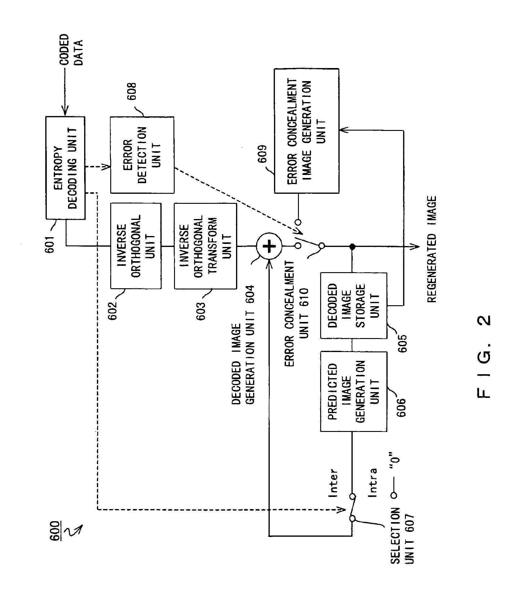
However, when an error occurs in the initial frame (the first frame, or the leading frame) of moving picture, the above described concealing process cannot be performed because the decoder 600 does not have the ‘data in the previous frame’.
That is, the quality of the moving picture is considerably deteriorated.
Therefore, once an error has occurred in the inter-frame prediction coding process, the undesired influence of the error on the image quality is propagated to the subsequent frames.
Therefore, when an error occurs in the first frame of moving picture and the error cannot be appropriately concealed in the conventional coding system, the undesired influence of the error on the quality of an image is propagated to the subsequent frames.
That is, when an error occurs in the first frame, it takes a long time to obtain an acceptable image even if no errors occur in the subsequent frames.
For example, assuming that an error occurs in a frame immediately after the moving picture has changed from a certain scene to quite a different scene, a similar problem occurs because the decoder does not contain effective ‘data in the previous frame’ to conceal the error.
Thus, if an error occurs in the first frame of moving picture or in a frame immediately after a scene changes into another scene in the conventional decoding system, it takes a long time to obtain an acceptable image.

Method used


Image

  • Encoder and decoder for moving picture
  • Encoder and decoder for moving picture
  • Encoder and decoder for moving picture

Examples


Embodiment Construction

[0059]Embodiments of the present invention are described below by referring to the attached drawings.

[0060]FIG. 4 shows the configuration of the communications system in which the encoder and the decoder according to an embodiment of the present invention are used. In this embodiment, moving picture data is transmitted from a terminal 10 to a terminal 20.

[0061]The terminal 10 comprises an encoder 11 for encoding moving picture data to be transmitted; a modulator 12 for modulating the coded data; and a transmitter 13 for transmitting the modulated data to a network. A modulation system is not limited, and a network can be either a public network or a private network such as a LAN. In addition, a transmission line can be a radio line, an optical fiber, or a metallic cable. On the other hand, the terminal 20 comprises a receiver 21 for receiving a signal from a network; a demodulator 22 for demodulating a received signal; and a decoder 23 for decoding the demodulated data and regenerat...


PUM


Abstract

A selection unit selects ‘0’ for the first through the (N−1)th frames, and selects a predicted image for the subsequent frames. Thus, an intra-frame coding process is performed on the first through the (N−1)th frames, and an adaptive coding process is performed on the subsequent frames. An information amount reduction unit reduces the amount of information about data in the first through the (N−1)th frames. An information amount adjustment unit stepwise increases the amount of information reduced by the information amount reduction unit.

Description

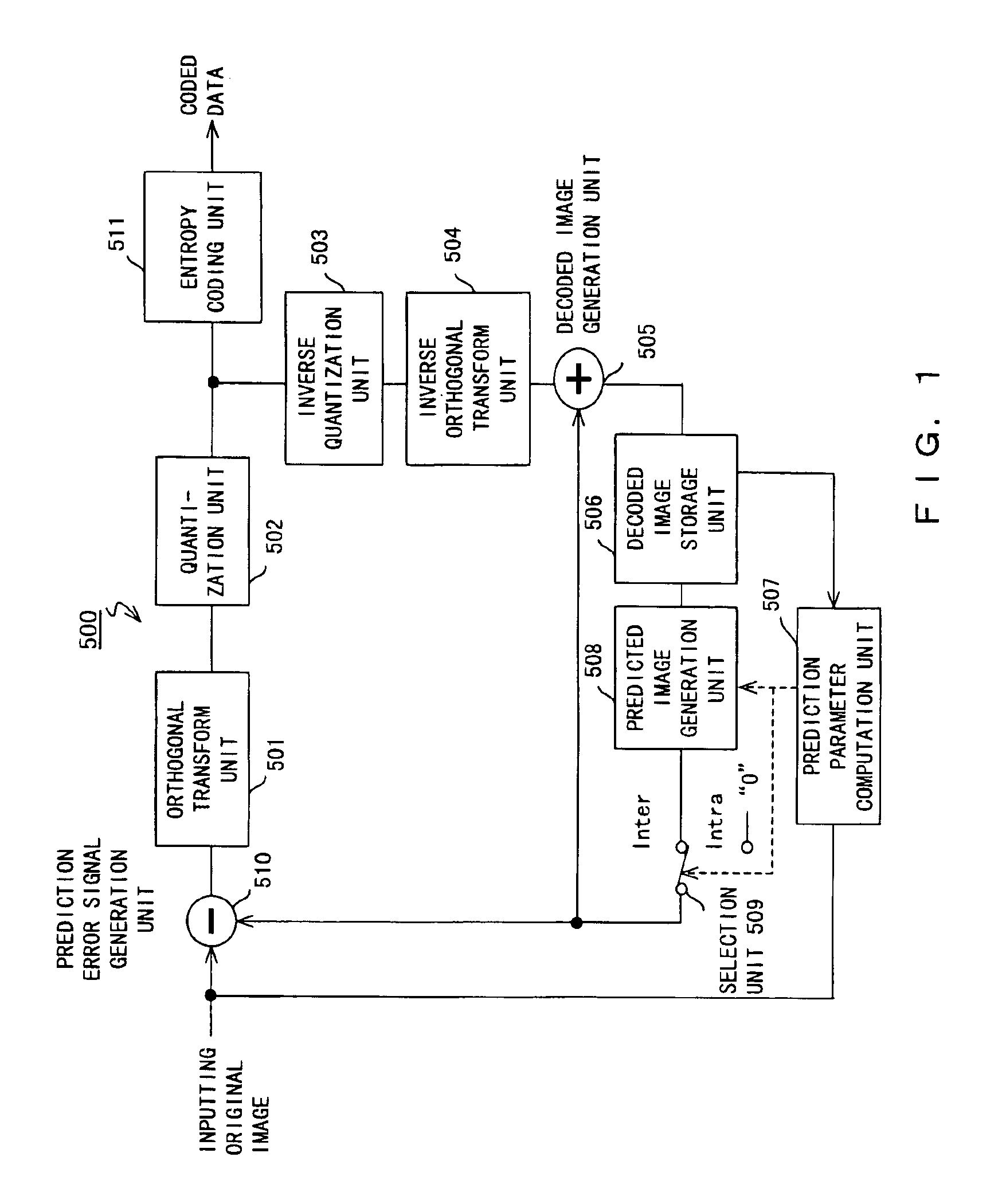
BACKGROUND OF THE INVENTION[0001]1. Field of the Invention[0002]The present invention relates to an encoder and a decoder for moving picture, and more specifically to a hybrid-type moving picture coding system for performing a motion compensating process and an orthogonal transforming process for each block obtained by dividing an input image into a plurality of blocks.[0003]2. Description of the Related Art[0004]Since the volume of moving picture data is normally large, a coding process is performed to compress the data when it is transmitted from a transmission device to a reception device, or when it is stored in a storage device.[0005]FIG. 1 is a block diagram of a conventional encoder. FIG. 2 is a block diagram of a conventional decoder for decoding moving picture data coded by the encoder shown in FIG. 1. In this example, the hybrid coding system realized by combining a motion compensation inter-frame predicting process and an orthogonal transforming process is explained as fo...

Claims


Application Information

Patent Timeline
Patent Type & Authority Patents(United States)
IPC IPC(8): G06T9/00H03M7/30H04N19/50H03M7/40H04N19/107H04N19/146H04N19/167H04N19/172H04N19/189H04N19/65H04N19/85H04N19/89H04N19/895
CPCH04N19/172H04N19/102H04N19/61H04N19/103H04N19/107H04N19/114H04N19/132H04N19/136H04N19/142H04N19/157H04N19/18H04N19/82H04N19/87H04N19/895H04N19/59
Inventor MORIMATSU, EISHINAKAGAWA, AKIRAICHIKI, ATSUSHIITOH, TAKASHIANAN, TAIZO
Owner FUJITSU LTD
Learn More