Pulsed light sources
a light source and pulse technology, applied in the direction of wave amplification devices, active medium shape and construction, laser details, etc., can solve the problems of mode distortion, non-linear distortion, gain saturation, mode distortion, etc., and achieve the effect of reducing the repetition rate of pulses and easing alignmen
Inactive Publication Date: 2005-07-12
UNIV OF SOUTHAMPTON
View PDF17 Cites 106 Cited by
- Summary
- Abstract
- Description
- Claims
- Application Information
AI Technical Summary
Benefits of technology
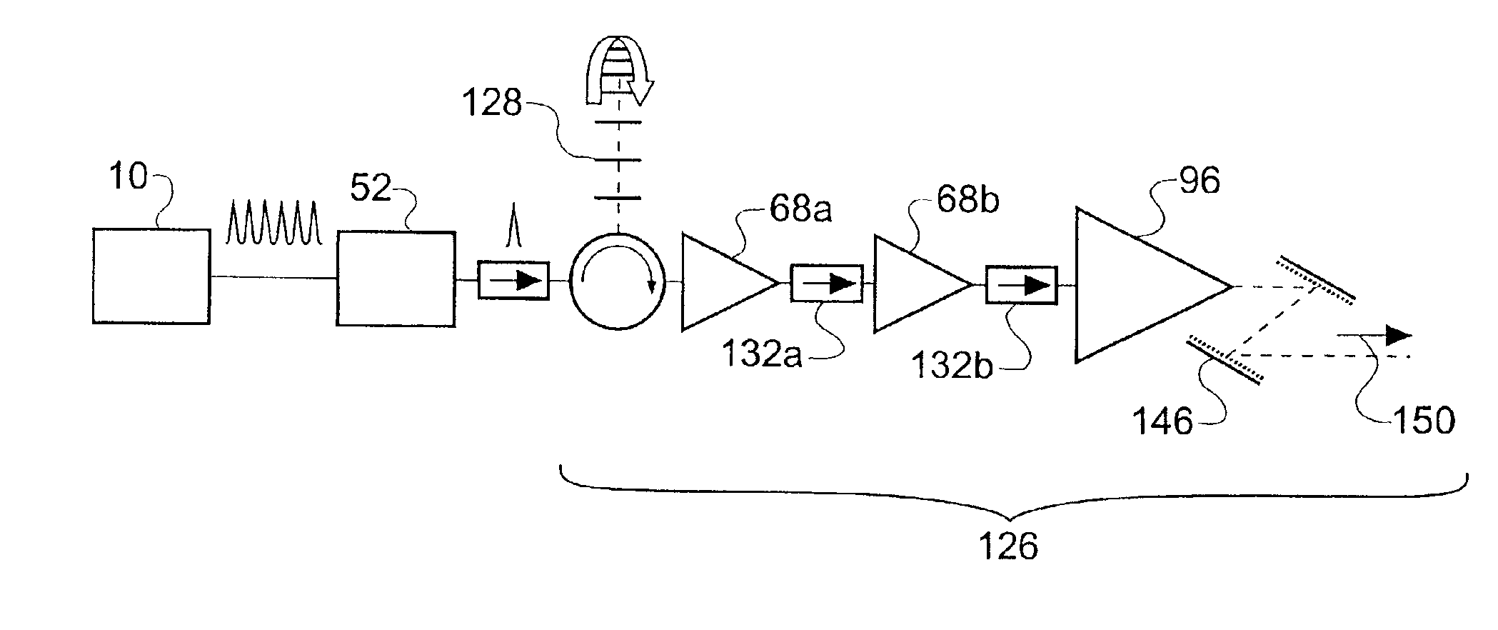
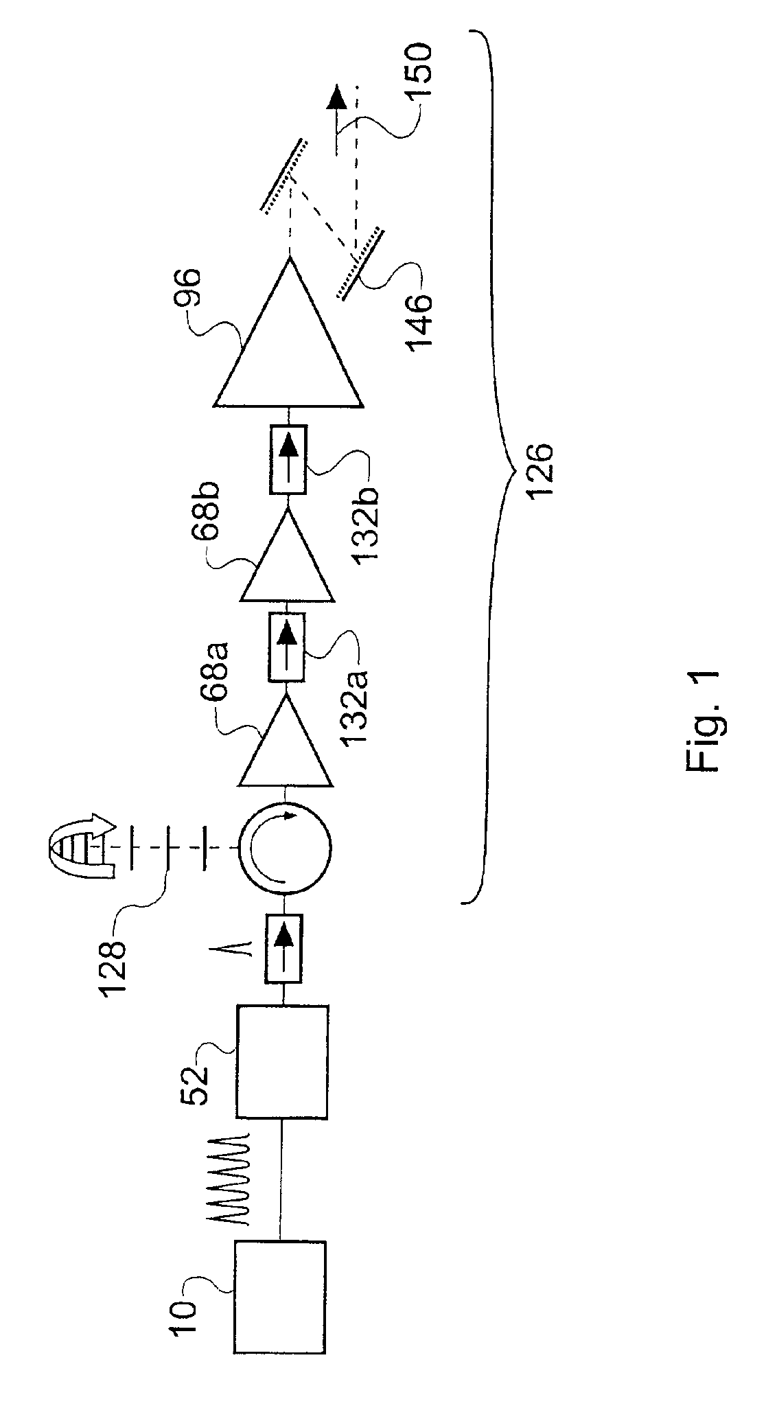
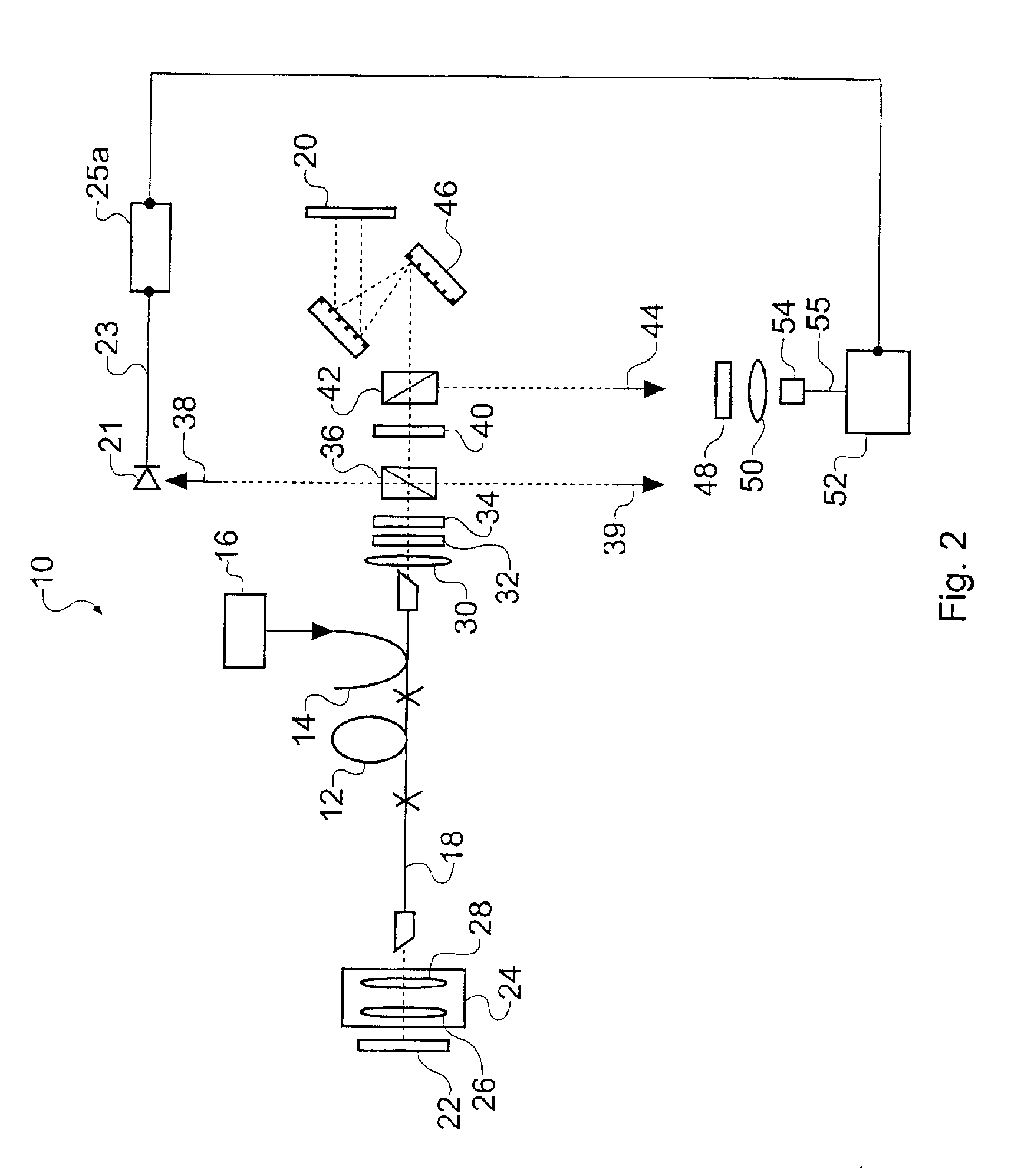
The invention provides a source of pulses of coherent radiation at a wavelength of approximately 1 μm. The source includes a pump source, a laser cavity, a pulse detector, a pulse selector, and at least one optical amplifier. The pulse detector generates a pulse selection signal, which is used to select the desired pulses. The optical amplifier amplifies the laser pulses and delivers them at a high energy. The laser cavity is modeledocked to generate laser pulses at a defined repetition rate. The pulse selector reduces the repetition rate of the laser pulses to avoid saturation problems. The at least one optical amplifier can be a cascade of amplifiers or a single amplifier. The invention allows for high-energy pulses at a wavelength of 1 μm.
Problems solved by technology
Laser oscillators tend to be unstable when operated so as to produce suitably high output powers directly.
The use of fiber amplifiers as amplification stages for pulsed laser sources presents its own problems, principally mode distortion, non-linear distortion and gain saturation.
Mode distortion arises if multimode fibers are used to increase energy storage [6].
Single mode fibers have good mode characteristics, but cannot provide such high energy storage.
Non-linear distortion in the amplifier gain medium arises at high peak pulse powers which result when higher overall energies are desired.
This reduces the pulse energies which can be achieved by the amplification process.
Method used
View moreImage
Smart ImageViewing Examples
Examples
further embodiment
[0201]Both the pulse stretcher and the pulse compressor can be omitted from the configuration of FIG. 27. This permits straightforward amplification of the pulse energy, although the quality of the amplified pulses may be poor.
Login to View More PUM
 Abstract
A source of pulses of coherent radiation at a wavelength of approximately 1 μm, comprises a pump source for producing pump light, a laser cavity comprising an Yb3+-doped gain medium arranged to receive the pump light, the laser cavity being modelocked to generate laser pulses at a defined repetition rate; a pulse detector arranged to generate a pulse selection signal indicative of the repetition rate; a pulse selector arranged to reduce the repetition rate of the laser pulses responsive to the pulse selection signal from the pulse detector by passing only selected ones of the laser pulses; and at least one optical amplifier for amplifying the laser pulses of reduced repetition rate. The at least one optical amplifier can be configured for chirped or parabolic pulse amplification.
Description
CROSS-REFERENCE TO RELATED APPLICATIONS[0001]This application claims benefit to United Kingdom National Application No. 0203798.4 filed in English on Feb. 18, 2002. The disclosure of this patent application is incorporated herein by reference.[0002]This application is related to U.S. patent application Ser. No. 10 / 120,965, filed on Apr. 10, 2002, and entitled “Sources of, and Methods for Generating, Optical Pulses.”BACKGROUND OF THE INVENTION[0003]1. Field of the Invention[0004]The invention relates to pulsed light sources, more especially, but not exclusively, to light sources that comprise optical fiber amplifiers for chirped pulse amplification.[0005]2. Related Art[0006]There is much demand for sources of pulses of light having both ultrashort durations (picosecond and femtosecond durations) and high energies. Many applications of ultrashort optical pulses require the peak powers, and hence the energies, of the pulses to be sufficient to excite a wide variety of non-linear optica...
Claims
Login to View More Application Information
Patent Timeline
 Patent Type & Authority Patents(United States)
IPC IPC(8): H01S3/06H01S3/067H01S3/098H01S3/102
CPCH01S3/06791H01S3/0057H01S3/0085H01S3/0675H01S3/06754H01S3/1024H01S3/1118H01S3/2316
Inventor RICHARDSON, DAVID JNILSSON, LARS JOHAN ALBINSSONLEFORT, LAURENTPRICE, JONATHAN HUGH VAUGHANMALINOWSKI, ANDREWIBSEN, MORTEN
Owner UNIV OF SOUTHAMPTON
Features
- R&D
- Intellectual Property
- Life Sciences
- Materials
- Tech Scout
- Unparalleled Data Quality
- Higher Quality Content
- 60% Fewer Hallucinations
Learn More Browse by: Latest US Patents, China's latest patents, Technical Efficacy Thesaurus, Application Domain, Technology Topic, Popular Technical Reports.
© 2025 PatSnap. All rights reserved.Legal|Privacy policy|Modern Slavery Act Transparency Statement|Sitemap|About US| Contact US: help@patsnap.com


