
Rotational stage with vertical axis adjustment

a technology of rotating stage and vertical axis, which is applied in the direction of instruments, photomechanical equipment, and material analysis through optical means, can solve the problems of increasing friction and consequently increasing actuating forces, difficult integration of conventional z-axis stage that utilizes guide rails, and difficult control of tilting movement of moving parts, etc., to achieve high rigidity, easy deformation, and high rigidity against tilt

Inactive Publication Date: 2005-07-12
THERMA WAVE INC
View PDF18 Cites 12 Cited by
  • Summary
  • Abstract
  • Description
  • Claims
  • Application Information

AI Technical Summary

Benefits of technology

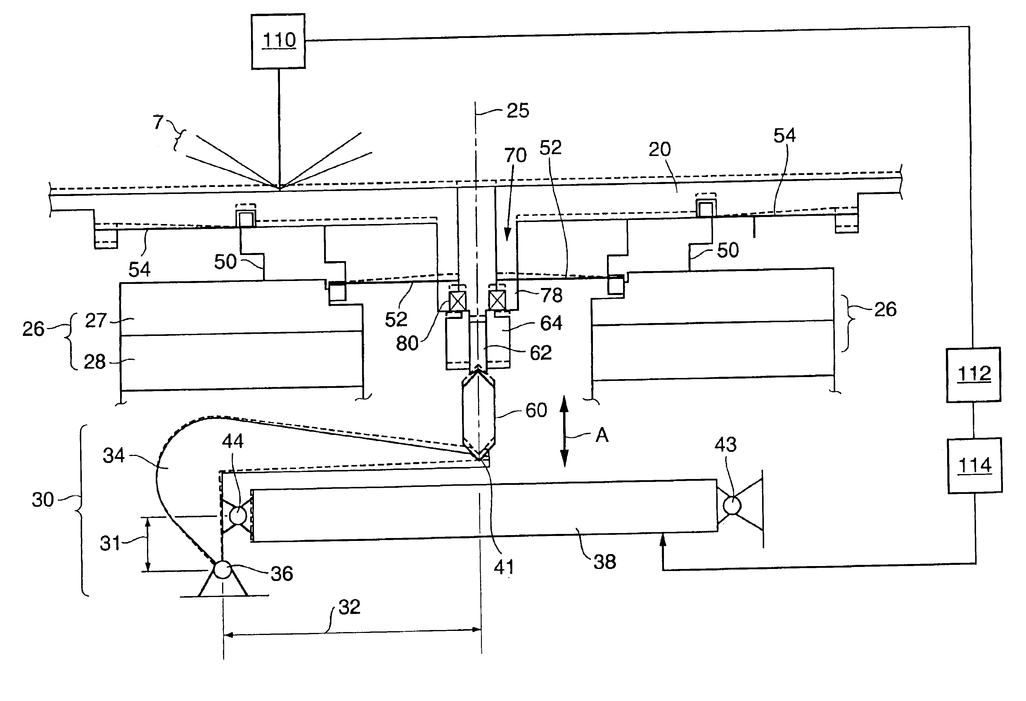
[0010]The chuck itself is guided along the axis of revolution within the rotating stage. Specifically configured and placed flexures or membranes elastically guide the chuck without any substantial friction. The membranes easily deflect in the vertical direction while being highly rigid in horizontal direction. Preferably, at least two ring shaped membranes are vertically positioned relative to each other. The horizontal stiffness of each membrane in combination with the vertical offset between them results in a high stiffness against tilt.
[0011]The rotationally symmetric design of the membranes allows them to be easily integrated into the generally rotationally symmetric design of the rotating stage. The relatively small mounting space required for mounting the membranes results in little additional volume and mass necessary for integrating the membrane rings in the rotating portion of the rotating stage.
[0012]The membranes provide a substantially friction free guidance of the chuck allowing for a smooth and precise actuation and adjustment. A horizontally oriented piezo stack is utilized to provide the vertical actuation of the chuck via a lever system, which amplifies and transforms the horizontal expansion of the piezo stack into a vertical movement of the required range. The vertical lever movement is transmitted to the chuck unit via a central linking assembly, which provides for initial adjustment and preload of the actuator to the chuck. The linking assembly also receives external vacuum and / or pressure air and transmits it into the chuck unit.

Problems solved by technology

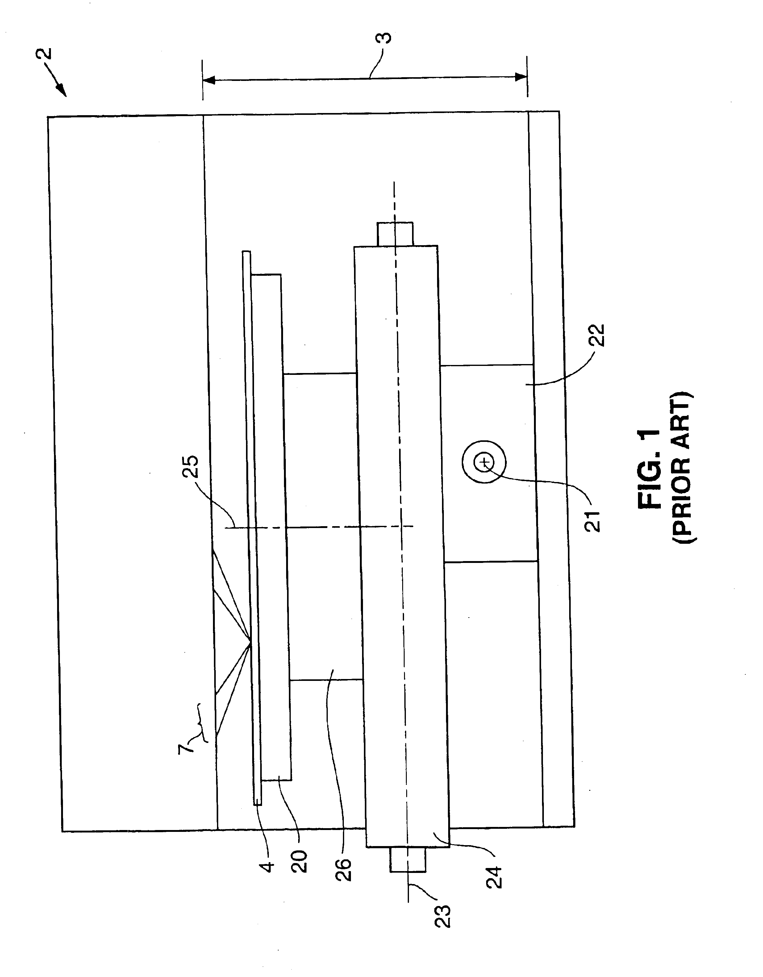
Since the motion system needs to be designed to fit within the available height 3, conventional Z-axis stages that utilize guide rails are difficult to integrate.
Where the length of the moving profile is limited by the available height, the tilting movement of the moving parts becomes hard to control.
In order to reduce the tilting movement, the contact pressure between the moving profile and the guide rails needs to be increased, which results in increased friction and consequently increased actuating forces.
High friction and actuating forces again reduce the movement resolution in Z-axis.
Providing Z-axis movement over that small a range with sliding or rolling guides still requires a relatively bulky and heavy assembly, which increases the moment of inertia of the motion system.

Method used


Image

  • Rotational stage with vertical axis adjustment
  • Rotational stage with vertical axis adjustment
  • Rotational stage with vertical axis adjustment

Examples


Embodiment Construction

[0023]FIG. 1 generally illustrates a wafer support and movement system 2 in which the subject invention can be incorporated. The system 2 is of the type that would be incorporated in a metrology tool for optically inspecting semiconductor wafers. Such metrology tools are described, for example, in U.S. Pat. Nos. 6,278,519 and 5,608,526, the disclosures of which are incorporated herein by reference. Such tools are capable of performing various measurements including spectroscopic reflectometry and spectroscopic ellipsometry.

[0024]In such metrology tools, a probe beam 7 is focused onto the sample surface. The reflected probe beam is monitored to evaluate characteristics of the sample. In these systems it is important to accurately focus the probe beam on the sample. In some systems, focusing is achieved by moving the optics within system 2 (not shown). In others, focusing is achieved by moving the stage system supporting the wafer in the Z-axis perpendicular to the sample surface. The...


PUM

PropertyMeasurementUnit
lengthaaaaaaaaaa
thicknessaaaaaaaaaa
widthaaaaaaaaaa

Abstract

A stage system is disclosed for supporting and positioning a semiconductor wafer for inspection in an optical metrology device. A chuck for supporting a wafer is mounted to the stage system. The stage system can move the chuck along two linear orthogonal axes. A rotational stage is also provided for rotating the chuck. A mechanism is provided for adjusting the vertical position of a chuck to allow for focusing of the probe beam of the metrology device. The vertical adjustment mechanism is designed so that it does impede the rotational positioning of the chuck.

Description

CLAIM OF PRIORITY[0001]The present application is a continuation of U.S. patent application Ser. No. 10 / 178,623, filed Jun. 24, 2002, ROTATIONAL STAGE WITH VERTICAL AXIS ADJUSTMENT, now U.S. Pat. No. 6,771,372 B1, which claims the benefit of U.S. Provisional Application Ser. No. 60 / 336,530, filed Nov. 1, 2001, ROTATIONAL STAGE WITH VERTICAL AXIS ADJUSTMENT, each of which is hereby incorporated herein by reference.FIELD OF INVENTION[0002]The present invention relates to metrology tools with rotating stages having integrated Z-axis adjustment for inspecting a wafer.BACKGROUND[0003]This invention relates to optical metrology tools of the type described in U.S. Pat. No. 6,278,519, incorporated herein by reference. Referring to prior art FIG. 1, these types of tools include a light source for generating a probe beam 7, which is focused onto a semiconductor wafer 4. Changes between the incident probe beam 7 and the reflected beam are monitored to evaluate characteristics of the sample 4.[...

Claims


Application Information

Patent Timeline
Patent Type & Authority Patents(United States)
IPC IPC(8): G01B11/00G03F7/20H01L21/687H01L21/68H01L21/67
CPCG01B11/00G03F7/707G03F7/70716H01L21/68H01L21/68792
Inventor TRABER, THOMAS
Owner THERMA WAVE INC
Learn More