Powder bell purge tube

a technology of purge tube and atomizer, which is applied in the direction of electrostatic spraying apparatus, burners, artistic surface treatment, etc., can solve the problems of unreliable and unsatisfactory cleaning of the atomizer with the air supplied through the external powder hose, and achieve the effect of less energy and considerably more efficiency

Inactive Publication Date: 2005-07-05
DURR SYST INC
View PDF13 Cites 0 Cited by
  • Summary
  • Abstract
  • Description
  • Claims
  • Application Information

AI Technical Summary

Benefits of technology

[0009]The introduction of the rinsing air during the coating pauses requires less energy and it is considerably more efficient than in the past, because it is led, without detour, through an external powder hose, conventionally having a length of up to 15 m, by a direct path into the atomizer. In addition, the air in this case is pure air which is not contaminated by residual powder and therefore deploys its full cleaning effect immediately and without delay. It is particularly advantageous that a possibility which did not exist in the past is now provided to achieve a targeted effective cleaning of the bell plate during production, using the corresponding brief rinse function, among other functions, which is known and conventionally used with wet lacquer atomizers, thanks to the practically delay-free supply of the rinsing air. During coating, the additional air channel, in contrast, can be used for the additional introduction of metered air prior to atomization and for changing the air proportion in the powder-air mixture independently of the conventional metering system. The possibilities provided thereby include acting against the mentioned instabilities and thus also the tendency to deposition of powder. In addition, by means of the additional air, it is possible to influence in a targeted manner, and to stabilize, in a simple manner, the size of the spray jet, the particle speed, and additional parameters.

Problems solved by technology

In powder atomizers, the problem consists of the fact that the coating material can be deposited not only in the supply lines and in the powder channel inside the atomizer, but also in the path of the powder-air mixture after its exit from the opening of the powder channel into a rotation atomizer, and particularly in the slit channel of the bell plate.
The disassembly and the manual cleaning of the bell plate are labor-intensive and time-consuming procedures, and they do not eliminate the risk of a narrowing of the cross section or even a clogging in the bell plate during the operation.
The cleaning of the atomizer with the air supplied through the external powder hose, in contrast, can turn out to be unreliable and unsatisfactory for various other reasons.
On the one hand, a considerable consumption of energy is required to convey the rinsing air through the external powder hose because of the latter's length, if a cleaning effect is to be achieved.
Furthermore, the air provided for the cleaning is, at least at the beginning, itself contaminated with such an amount of residual powder from the hose that a cleaning effect occurs only after a relatively long time, which is then lost for the coating operation.
During the coating operation, other instabilities can occur besides the risk of clogging.
Because, in known rotation atomizers, the proportion of air in the powder-air mixture is determined only by the metering system (for example, injector or powder pump), pump effects and undesired changes in the powder-spray jet can occur, especially in conveyance systems which use little air.

Method used


Image

  • Powder bell purge tube
  • Powder bell purge tube

Examples


Embodiment Construction

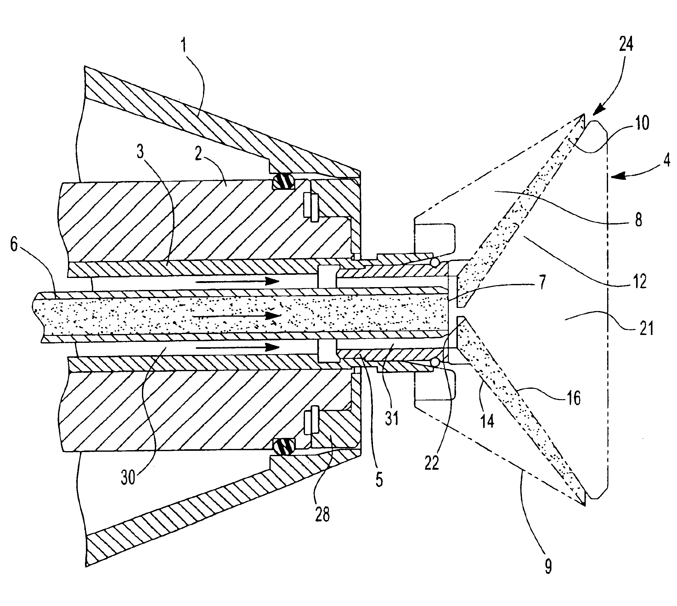
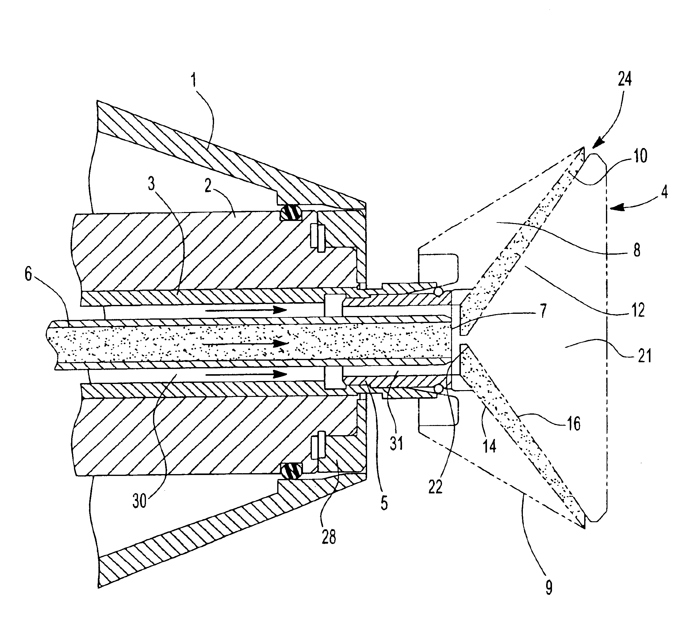
[0012]The rotation atomizer which is only partially represented can correspond, with the exception of the characteristics of the invention explained below, to the known atomizer of the type Durr / Behr N34040001. It contains, like the latter, a front atomization housing 1 containing the drive turbine 2 with the pivoted hollow shaft 3. In the free open end of the hollow shaft 3, the hollow cylindrical hub part 5 of the atomizer bell 4 is attached. A cylindrical pipe 6, which functions as a powder channel of the atomizer, extends coaxially through the hollow shaft 3 into the hub part 5 of the bell 4, where it opens, as shown in the representation, at 7 axially outside the atomization housing 1. The powder pipe 6 is connected to the atomizer at a powder hose (not shown) arriving from an external air and powder supply.

[0013]The high voltage generator (not shown) for the atomization bell 4 charged to the usual potential can also be accommodated in the atomizer, for example, in the housing ...


PUM

PropertyMeasurementUnit
lengthaaaaaaaaaa
pressureaaaaaaaaaa
voltage potentialaaaaaaaaaa

Abstract

In a powder atomizer for series coating of workpieces, additional air is led from a separate channel into the path of the powder-air mixture which exits from the powder channel of the atomizer, air which can be used during the coating to influence and change the mixture and, during pauses in the coating, as rinsing air for cleaning, for example, the powder path leading through an atomization bell.

Description

RELATED APPLICATIONS[0001]This application claims priority to German Patent Registration No. AN0103 DE filed Mar. 8, 2001 and assigned Patent No. PA 101112092. This application is a continuation of Ser. No. 10 / 053,455 filed Oct. 25, 2001 now abandoned.BACKGROUND OF THE INVENTION[0002]The subject invention relates to a powder atomizer as well as to a method for the series coating of workpieces with powdered coating material according to the preamble of the independent claims. In particular, the invention relates to an electrostatic rotation atomizer with a powder atomization bell which, during operation, is under a high-voltage potential, and which is like the ones used for the series coating of car bodies.[0003]In such rotation atomizers, it is known (Dürr / Behr type N34040001) that the powder-air mixture is supplied through external hoses and led within the atomizer through the hollow shaft of the drive turbine in a slit-shaped channel in the inside of the bell plate attached to the...

Claims


Application Information

Patent Timeline
Patent Type & Authority Patents(United States)
IPC IPC(8): B05B5/04B05B7/02B05B3/02B05B3/10B05B7/08
CPCB05B3/1064B05B5/0407B05B5/0418B05B7/0815B05B3/1092B05B5/0426
Inventor DUERR, THOMAS
Owner DURR SYST INC
Why Eureka
Try Eureka