
Auger type ice-making machine

a technology of ice-making machines and ice-making chambers, which is applied in the direction of ice production, ohmic-resistance heating, lighting and heating apparatus, etc. it can solve the problems of electric leakage and wire breakage, poor adhesion of the attachment parts to the heater, and inability to function as a melting heater. , to achieve the effect of smooth ice-making

Inactive Publication Date: 2005-07-05
HOSHIZAKI ELECTRIC CO LTD
View PDF8 Cites 5 Cited by
  • Summary
  • Abstract
  • Description
  • Claims
  • Application Information

AI Technical Summary

Benefits of technology

[0007]An object of the present invention is to provide an auger type ice-making machine which is capable of discharging ice smoothly by causing a heater which melts ice following manufacture in an ice compression head portion to function reliably.
[0009]Here, when the cast-in heating means comprise an interior heater which generates heat by electricity, an advantage is gained in that heat control through electric power can be performed with ease.
[0010]If the cast-in heating means comprise a heater which generates heat by circulating a heated fluid (a hot fluid: hot gas or a liquid such as warm oil) through its interior, then energy can be saved since electric power is not used, and there is no need to provide measures against electric leakage caused by condensation. Further, since the cast-in heater is constituted chiefly by only two parts, the pipe and the cast material (aluminum material or the like), component costs and the number of manufacturing processes can be greatly reduced. Since it is also possible to make use of the heat that is generated by a refrigerating unit of the ice-making machine, the cast-in heater can also be used as a cooling component. In this case, the cast-in heater functions not only as an ice-melting heater, but also as a heat exchanger, thus contributing to an improvement in the ice-making performance.

Problems solved by technology

However, when such a heater is wrapped irregularly or wrapped around an attachment part (the upper outer peripheral surface of the ice-making cylinder) having a complex form (with stepped surface), adhesion thereof to the attachment part may be poor, as a result of which the heat from the heater may not be sufficiently transmitted to the ice compression head through the ice-making cylinder, and the heater may not be able to function sufficiently as a melting heater.
Another concern is that due to the lack of adhesion, the heater may overheat, hastening the deterioration of the silicone and causing electric leakage and wire breakage.

Method used


Image

  • Auger type ice-making machine
  • Auger type ice-making machine
  • Auger type ice-making machine

Examples


Embodiment Construction

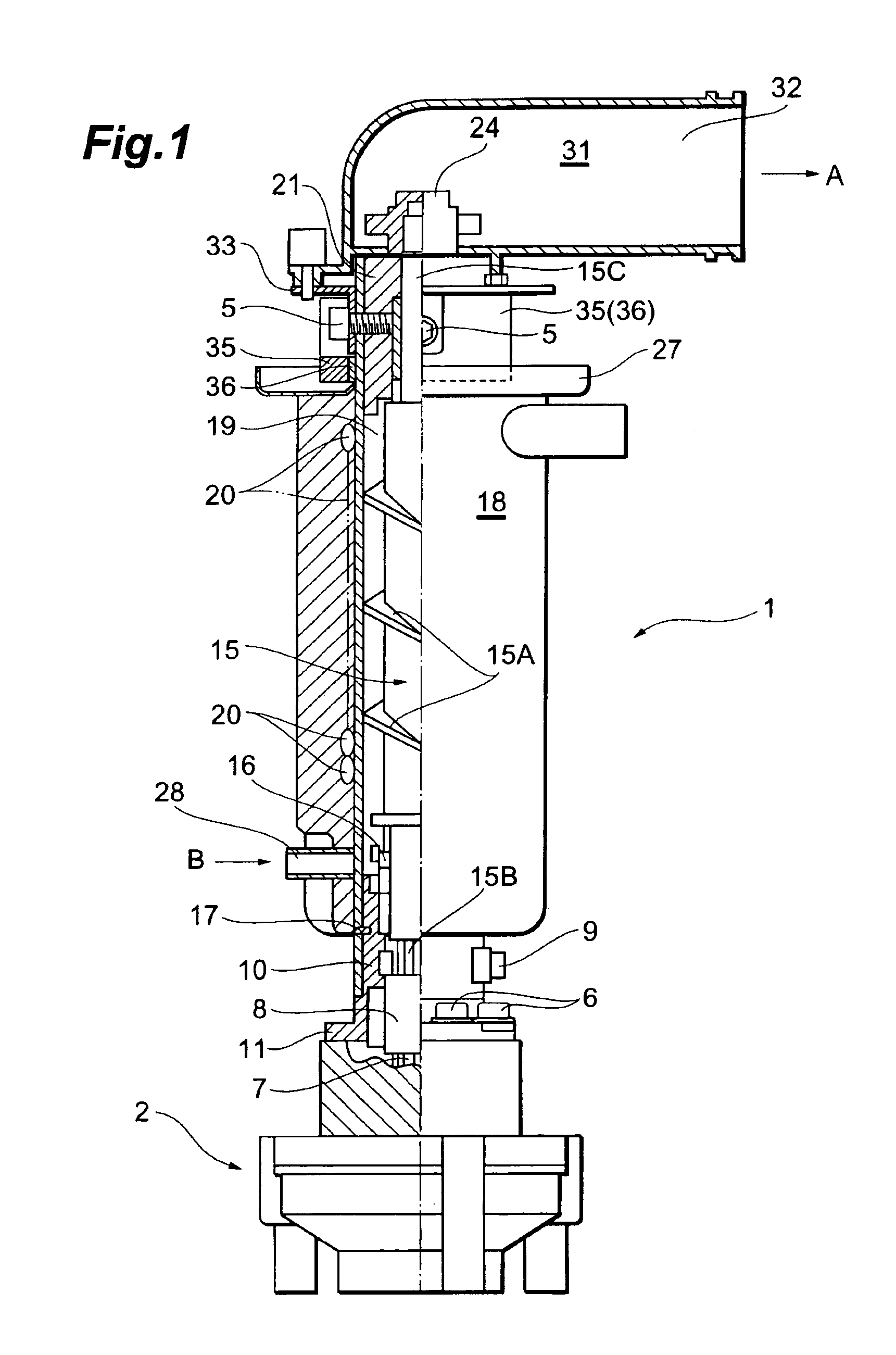
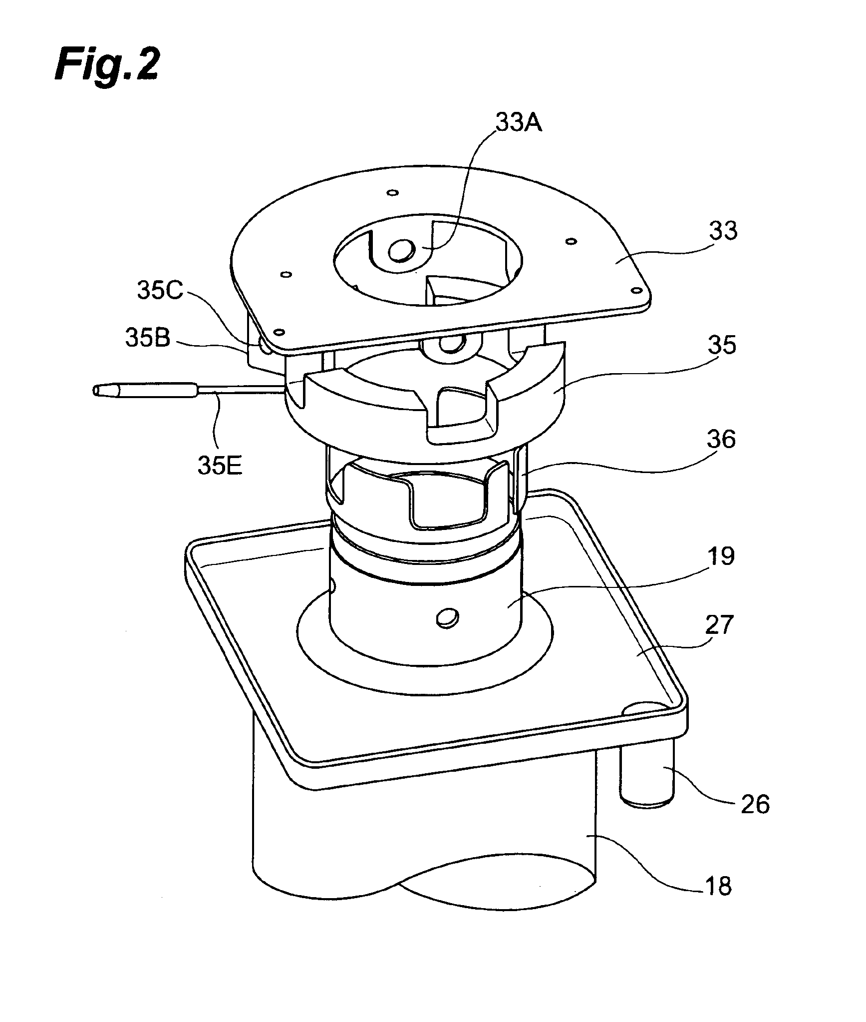
[0024]Embodiments of the auger type ice-making machine of the present invention will be described below with reference to the drawings. First, the constitution of the auger type ice-making machine of the present embodiments will be described on the basis of FIGS. 1 and 2. FIG. 1 is a sectional view of the auger-type ice-making machine (a side view is shown to the right of the figure). FIG. 2 is an exploded perspective view of the vicinity of an ice compression head serving as a main part of the present invention. FIG. 3 is a perspective view of the vicinity of the ice compression head following assembly.

[0025]As is shown in FIG. 1, a geared motor 2 is disposed in the lower portion of an auger type ice-making machine 1. In this geared motor 2, a driving motor and a speed reduction gear are constructed as an integral unit. The lower end of a spline joint 8 is attached to an output shaft 7 of the speed reduction gear, and the spline joint 8 and a lower end portion 15B of an auger 15 ar...


PUM


Abstract

An auger type ice-making machine of the present invention comprises an ice-making cylinder which accommodates an auger rotatably in the interior thereof, an ice compression head which supports the upper end portion of the auger rotatably, and which is disposed in the upper portion of the ice-making cylinder, and a cast-in heater which is attached to the outer peripheral surface of an accommodating portion for the ice compression head of the ice-making cylinder. According to the present invention, the use of a cast-in heater enables heat to be reliably transmitted to the ice compression head, whereby the compressed ice can be melted and ice can be discharged smoothly.

Description

BACKGROUND OF THE INVENTION[0001]1. Field of the Invention[0002]The present invention relates to an auger type ice-making machine which manufactures chip-form or flake-form ice by freezing ice-making water that is supplied to the interior of an ice-making cylinder while rotating an auger in the interior of the ice-making cylinder via a geared motor.[0003]2. Related Background Art[0004]Various sorts of auger type ice-making machines have been proposed in the past (see Japanese Patent Application Laid-Open No. H10-2645 and Japanese Patent Application Laid-Open No. S59-18363). In such auger type ice-making machines, an auger (screw) is supported rotatably inside a tubular ice-making cylinder between an ice compression head (also known as a fixed blade) that is disposed in the upper portion of the ice-making cylinder and a housing that is disposed in the lower portion of the ice-making cylinder. Then, while ice-making water that is supplied to the interior of the ice-making cylinder is ...

Claims


Application Information

Patent Timeline
IPC IPC(8): F25C1/12F25C5/00F25C1/14F25C5/08
CPCF25C1/147F25C5/08
Inventor SUGIE, HIROYUKIMATSUO, KAZUNORIMIZUTANI, YASUKINOMURA, TOMOHITOHAMAJIMA, MIKA
Owner HOSHIZAKI ELECTRIC CO LTD
Learn More