
Pneumatic-spring wheel-suspension leg

a technology of pneumatic springs and suspension legs, applied in the direction of resilient suspensions, vehicle springs, vibration dampers, etc., can solve the problem of complex design with a density of controls

Inactive Publication Date: 2005-06-28
THYSSENKRUPP BILSTEIN
View PDF5 Cites 10 Cited by
  • Summary
  • Abstract
  • Description
  • Claims
  • Application Information

AI Technical Summary

Benefits of technology

[0003]The advantages of the present invention are that the spring's performance curve can also be varied between soft and hard, whereby the curve switches automatically to hard when the wheel kicks out considerably toward the vehicle's body and to soft once the wheel has mostly stopped executing such long-wave motions.

Problems solved by technology

In pneumatically sprung vehicles in particular, which must have as soft a suspension as possible, this means that the dashpot must have as wide a range of controls as possible on the other hand, which can lead to complicated designs with a density of controls.

Method used


Image

  • Pneumatic-spring wheel-suspension leg
  • Pneumatic-spring wheel-suspension leg
  • Pneumatic-spring wheel-suspension leg

Examples


Embodiment Construction

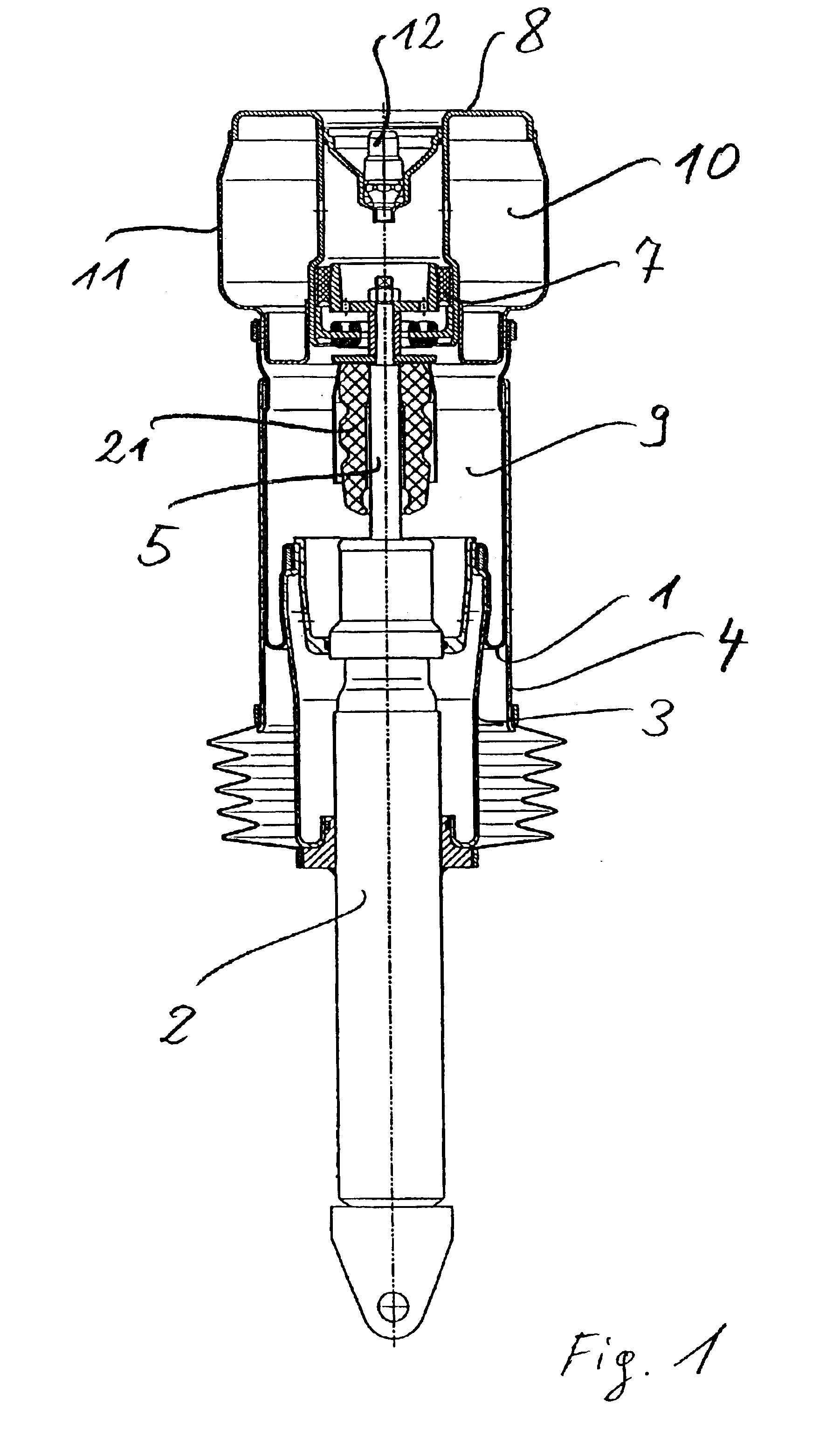
[0007]Pneumatic-spring wheel-suspension legs preferably include a pneumatic spring that accommodates a hydraulic dashpot. As will be evident from FIG. 1, the spring essentially comprises a bellows 1 hermetically sealed off at one end from a pneumatic cylinder 2 and at the other from a fastener that attaches the spring to a vehicle's chassis. The end of bellows 1 adjacent to the dashpot extends inward by way of a roll-off jacket 3 and outward by way of a cylindrical holder 4. The dashpot consists of a cylinder 2 and of a piston rod 5 that travels into and out of it. At the end of the rod is a suspension bell 6 that is connected on the outside and preferably axially resilient to a supporting cylinder 8 by way of a rocker 7. Bell-supporting cylinder 8 is appropriately attached to an unillustrated location on the chassis.

[0008]Essentially above rod-suspension bell 6, bellows 1 accommodates two pneumatics chambers 9 and 10. Chamber 10 is invariable in volume and is essentially supported ...


PUM


Abstract

A pneumatic-spring wheel-suspension leg for motor vehicles. The leg comprises a bellows (1) that can be rolled up over a jacket (3) and accommodates a pneumatics chamber (9), a hydraulic dashpot inside the bellows or jacket, and a piston rod (5) that travels into and out of the dashpot and is attached axially and resiliently directly or indirectly at one end to the vehicle's chassis. The object is to relieve the dashpot of difficult attenuation tasks when a hard wheel suspension is necessary. The leg accordingly includes another pneumatics chamber (10) and the communication between the two pneumatics chambers can be partly or entirely blocked by a valve.

Description

BACKGROUND OF THE INVENTION[0001]The present invention concerns a pneumatic-spring wheel-suspension leg. Such legs are particularly employed in smoothly suspended vehicles. A device of this genus is disclosed in German 19 819 642 A2. The “spring” is essentially a bellows with connections and attachments at one end and accommodating a hydraulic oscillating dashpot. One end of the dashpot extends out of the bellows and is also provided with connections and attachments.[0002]To adapt its performance curve or degree of attenuation to the vehicle's operation in terms of road conditions, speed, and other parameters, the dashpot is provided with controls. Controls are especially necessary when the road is very rough, powerfully kicking the wheels out. To ensure satisfactory adhesion of the wheels to the road accordingly, the suspension's performance curve must be as hard as possible. In pneumatically sprung vehicles in particular, which must have as soft a suspension as possible, this mean...

Claims


Application Information

Patent Timeline
Patent Type & Authority Patents(United States)
IPC IPC(8): F16F9/05F16F9/02B60G15/12
CPCB60G15/12F16F9/05B60G2202/314B60G2500/2041B60G2500/22B60G2204/1262
Inventor FRITZ, MICHAEL
Owner THYSSENKRUPP BILSTEIN
Learn More