
Method for eliminating strong ambient light in aircraft cockpits

a technology for aircraft cockpits and ambient light, applied in the field of display devices, can solve the problems of failure of failure of ag, linear or circular polarizers, and failure of ag at higher levels of illumination, so as to minimize the effect of light on the display device and minimize reflection

Inactive Publication Date: 2005-06-21
HONEYWELL INT INC
View PDF21 Cites 15 Cited by
  • Summary
  • Abstract
  • Description
  • Claims
  • Application Information

AI Technical Summary

Benefits of technology

[0007]In further embodiments, the display device comprises a LCD display that is manufactured with an integrated polarizer. The first sheet of polarizing material is then attached with a polarization pass axis orientation substantially perpendicular to that of the integrated polarizer. Such an orientation is easily obtained by simply moving the first sheet of polarizing material to a position that substantially minimizes the effect of light on the display device.
[0008]When a CRT display is utilized, the second polarized material comprises a second sheet of polarizing material comprises a separate transparent material which is properly positionable proximate the CRT to minimize reflection from bright ambient light.

Problems solved by technology

Coatings such as AR, AG, and linear or circular polarizers work under low or moderate ambient light conditions, but fail at higher levels of illuminance, such as 10 K foot candles.

Method used


Image

  • Method for eliminating strong ambient light in aircraft cockpits
  • Method for eliminating strong ambient light in aircraft cockpits

Examples


Embodiment Construction

[0011]In the following description, reference is made to the accompanying drawings that form a part hereof, and in which is shown by way of illustration specific embodiments in which the invention may be practiced. These embodiments are described in sufficient detail to enable those skilled in the art to practice the invention, and it is to be understood that other embodiments may be utilized and that structural, logical and electrical changes may be made without departing from the scope of the present invention. The following description is, therefore, not to be taken in a limited sense, and the scope of the present invention is defined by the appended claims.

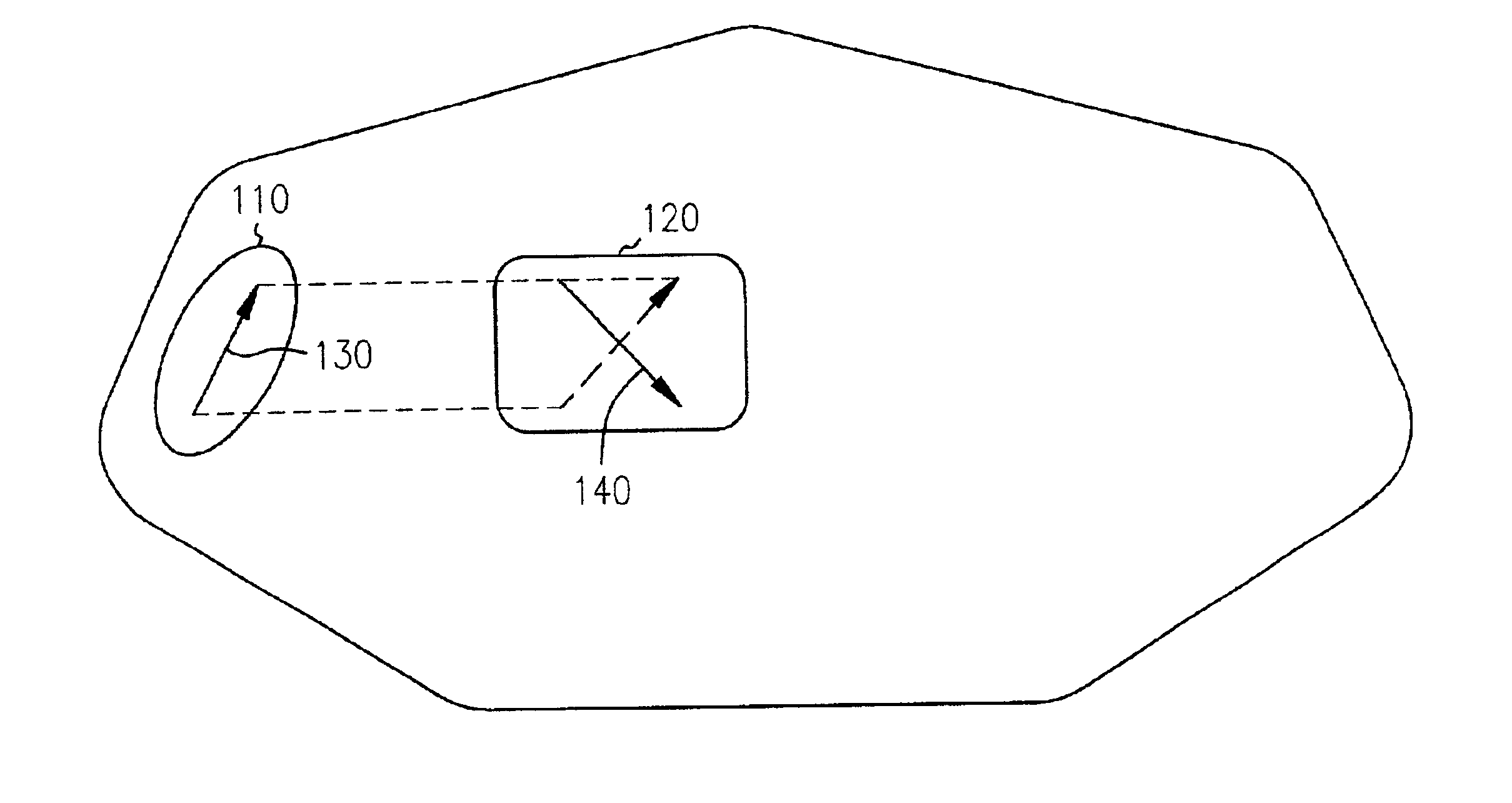
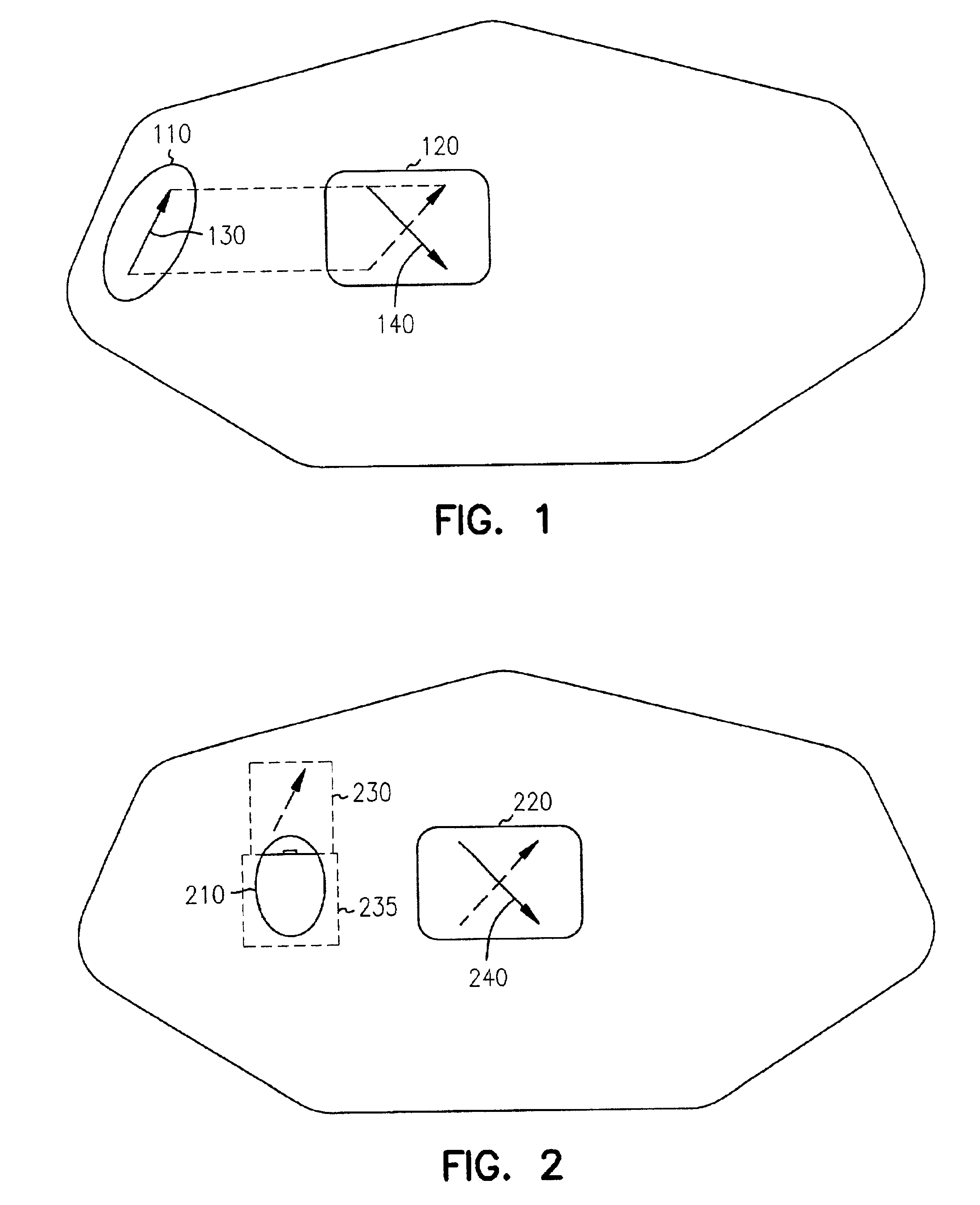
[0012]FIG. 1 is a block diagram of a cockpit having a light source 110, such as a window, and a display device 120, which receives ambient light from light source 110. In prior systems, the ambient light would overwhelm the visibility of information viewable on the display device. In the present invention, a first sheet of pol...


PUM

PropertyMeasurementUnit
pressure sensitiveaaaaaaaaaa
transmittanceaaaaaaaaaa
transparentaaaaaaaaaa

Abstract

Light is polarized in perpendicular directions between a source of light and a users viewing of information on a display device. A first sheet of polarized material is placed at the source of the light, such as a window in a cockpit. A second sheet of polarized material is attached or integral to a display device. The pass axis of the second sheet is oriented substantially perpendicular to pass axis of the first sheet.

Description

FIELD OF THE INVENTION[0001]The present invention relates to display devices, and in particular to the use of two polarizers to ensure visibility of the display in strong ambient light.BACKGROUND OF THE INVENTION[0002]Display devices, such as liquid crystal displays (LCDs) and cathode ray tubes (CRTs) are used to display data to users. Bright environments, such as cockpits of aircraft often contain such display devices. In some environments, the visibility of information is critical. In aircraft, good visibility of the information on display devices can be critical to safe operation of the aircraft.[0003]Prior solutions for minimizing the effect of cockpit ambient light include application of various films or coatings only to display surfaces. Coatings such as AR, AG, and linear or circular polarizers work under low or moderate ambient light conditions, but fail at higher levels of illuminance, such as 10 K foot candles.[0004]There is a need for enhanced visibility of information on...

Claims


Application Information

Patent Timeline
Patent Type & Authority Patents(United States)
IPC IPC(8): G02F1/1335G02F1/13G02B27/28
CPCG02B27/281G02F1/133528Y10S359/90
Inventor KOLOSOWSKY, ALEKSANDRA
Owner HONEYWELL INT INC
Learn More