
Method for eliminating strong ambient light in aircraft cockpits

a technology for aircraft cockpits and ambient light, applied in the field of display devices, can solve the problems of failure of linear or circular polarizers, failure of a and failure of ag linear or circular polarizers at higher levels of illumination, so as to minimize the effect of light on the display device, minimize reflection, and minimize the effect of light reflection

Inactive Publication Date: 2006-03-16
HONEYWELL INT INC
View PDF7 Cites 11 Cited by
  • Summary
  • Abstract
  • Description
  • Claims
  • Application Information

AI Technical Summary

Benefits of technology

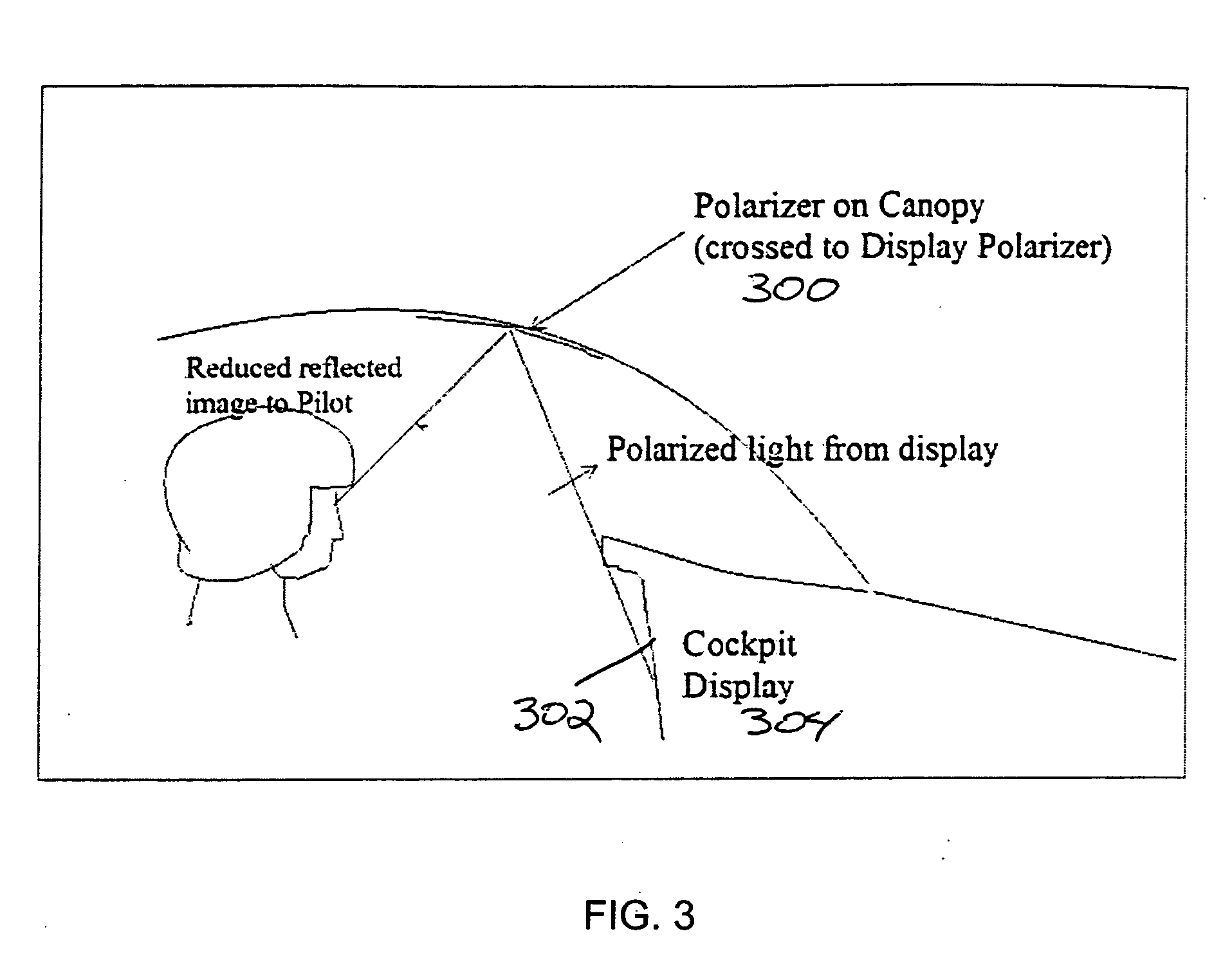
The patent describes a method for displaying information on a display device in a way that is easy to see and minimizes reflection from bright ambient light. This is achieved by using two sheets of polarized material placed at the source of light and proximate to the display device. The first sheet is attached to the side window or canopy with an adhesive and its polarization pass axis is oriented perpendicular to the second sheet, which is attached to the display device. This orientation ensures that the bright light from the source is directed towards the display device without causing reflection. The second sheet can also be a separate transparent material placed proximate to the CRT display to minimize reflection from bright ambient light. Overall, this method provides a clear and safe display in various lighting conditions.

Problems solved by technology

Coatings such as AR, AG, and linear or circular polarizers work under low or moderate ambient light conditions, but fail at higher levels of illuminance, such as 10K foot candles.
The mechanical filters can have negative effects such as low transmission and can cause interference patterns (moire) between the display pixel array and the micro-louver pitch.

Method used


Image

  • Method for eliminating strong ambient light in aircraft cockpits
  • Method for eliminating strong ambient light in aircraft cockpits
  • Method for eliminating strong ambient light in aircraft cockpits

Examples


Embodiment Construction

)

[0018] In the following description, reference is made to the accompanying drawings that form a part hereof, and in which is shown by way of illustration specific embodiments in which the invention may be practiced. These embodiments are described in sufficient detail to enable those skilled in the art to practice the invention, and it is to be understood that other embodiments may be utilized and that structural, logical and electrical changes may be made without departing from the scope of the present invention. The following description is, therefore, not to be taken in a limited sense, and the scope of the present invention is defined by the appended claims.

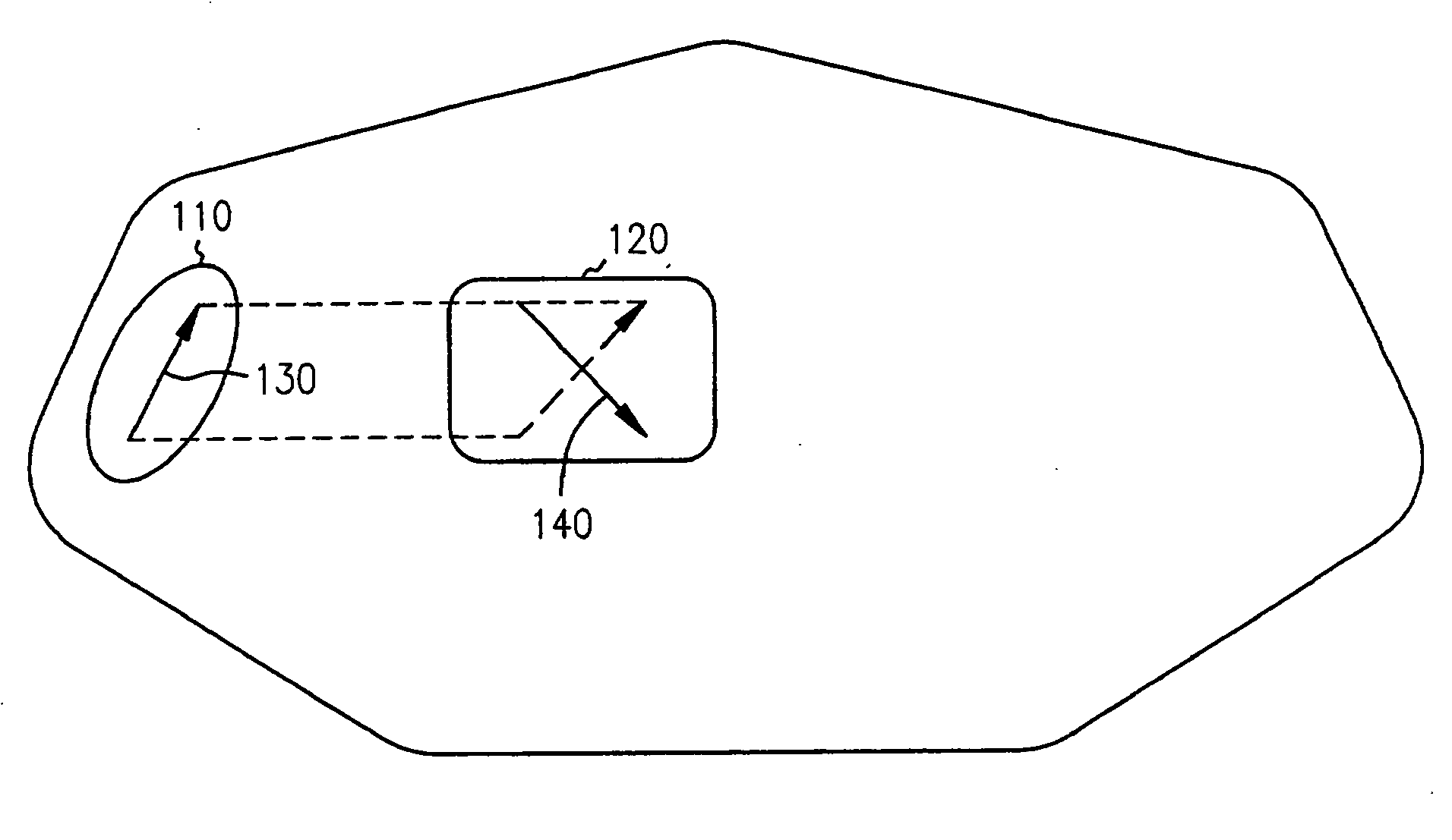
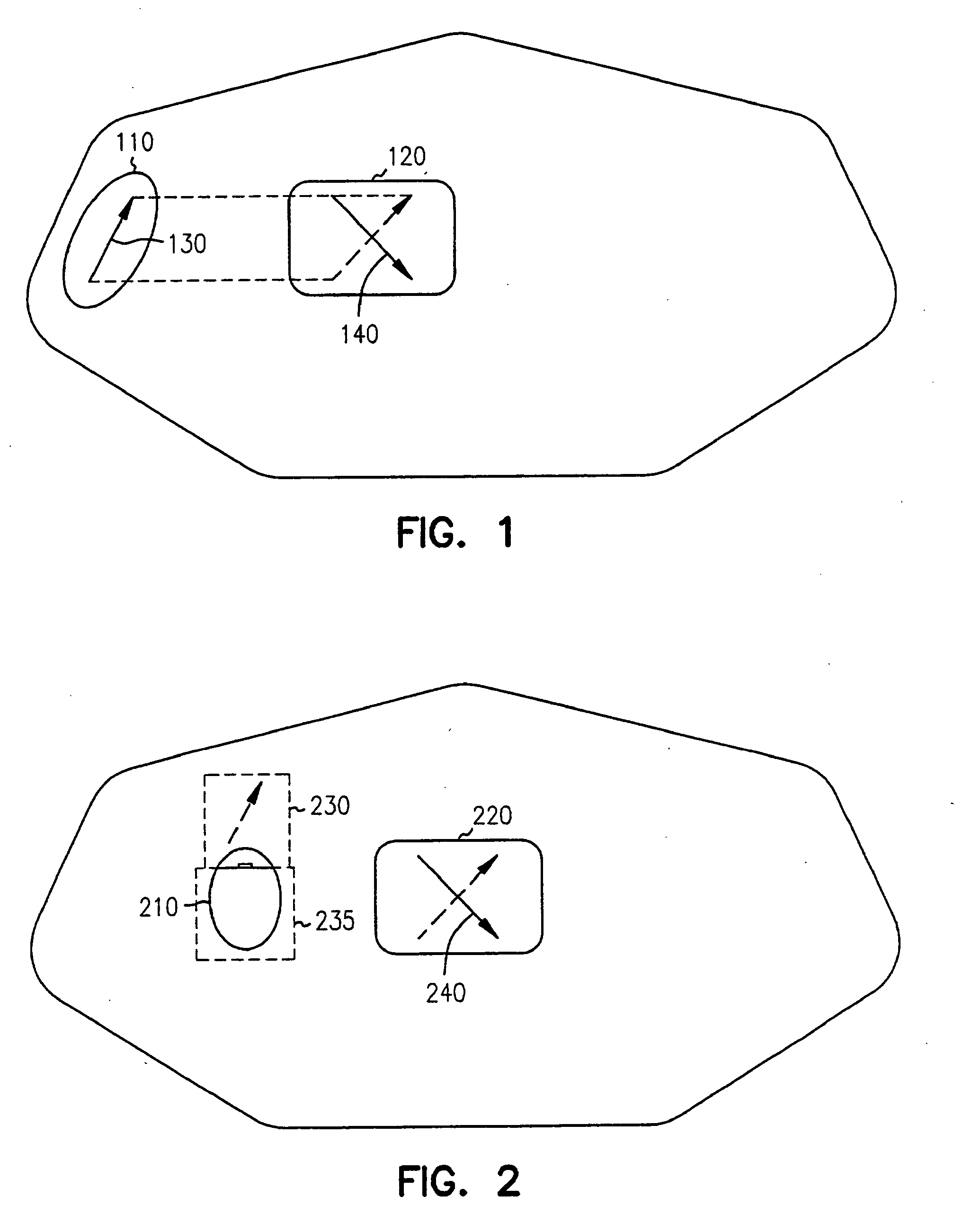
[0019]FIG. 1 is a block diagram of a cockpit having a light source 110, such as a window, and a display device 120, which receives ambient light from light source 110. In prior systems, the ambient light would overwhelm the visibility of information viewable on the display device. In the present invention, a first sheet of ...


PUM

PropertyMeasurementUnit
reflectionsaaaaaaaaaa
specific anglesaaaaaaaaaa
transmissionaaaaaaaaaa

Abstract

Light is polarized in perpendicular directions between a source of light and a users viewing of information on a display device. A first sheet of polarized material is placed at the source of the light, such as a window in a cockpit. A second sheet of polarized material is attached or integral to a display device. The pass axis of the second sheet is oriented substantially perpendicular to pass axis of the first sheet. Additionally, the same methodology can be used to minimize reflections from cockpit displays at night.

Description

CROSS REFERENCE TO RELATED APPLICATIONS [0001] This application is a continuation-in-part application of U.S. Pat. No. 6,909,544, entitled “Device For Eliminating Strong Ambient Light in Aircraft”, filed Apr. 16, 2002, which is herein incorporated by reference in its entirety.BACKGROUND OF THE INVENTION [0002] 1. Field of the Invention (Technical Field) [0003] The present invention relates to display devices, and in particular to the use of two polarizers to ensure visibility outside of the cockpit world from inside the cockpit by minimizing reflected images of avionic displays on the aircraft canopy. [0004] 2. Background Art [0005] Display devices, such as liquid crystal displays (LCDs) and cathode ray tubes (CRTs) are used to display data to users. Aircraft are used in both day and night conditions. Bright environments, such as cockpits of aircraft often contain such display devices. In some environments, the visibility of information is critical. In aircraft, good visibility of t...

Claims


Application Information

Patent Timeline
Patent Type & Authority Applications(United States)
IPC IPC(8): G02B5/30G02B27/28G02F1/1335
CPCG02F1/133528G02B27/281
Inventor KOLOSOWSKY, ALEKSANDRAWOOD, TEDDY J.
Owner HONEYWELL INT INC
Learn More