Amplification circuit for increasing variable reluctance sensor output

a variable reluctance and output technology, applied in the field of variable reluctance sensors, can solve the problems of low signal-to-noise ratio, substantial high-frequency electrical noise produced by other engine components, and various problems of related art vrs

Inactive Publication Date: 2005-06-21
CATERPILLAR INC
View PDF14 Cites 6 Cited by
  • Summary
  • Abstract
  • Description
  • Claims
  • Application Information

AI Technical Summary

Problems solved by technology

However, the related art VRS has various problems and disadvantages.
Typically, there is substantial high-frequency electrical noise produced by other engine components (e.g., firing injectors or local power supplies on board the engine).
Thus, at low speeds, there is a low signal-to-noise ratio, and the voltages induced by the high-frequency noise sources will interfere with the operation of the VRS.
As a result, engine speed cannot be monitored in an accurate manner during the startup period and during other low operating speed periods.

Method used


Image

  • Amplification circuit for increasing variable reluctance sensor output
  • Amplification circuit for increasing variable reluctance sensor output
  • Amplification circuit for increasing variable reluctance sensor output

Examples


Embodiment Construction

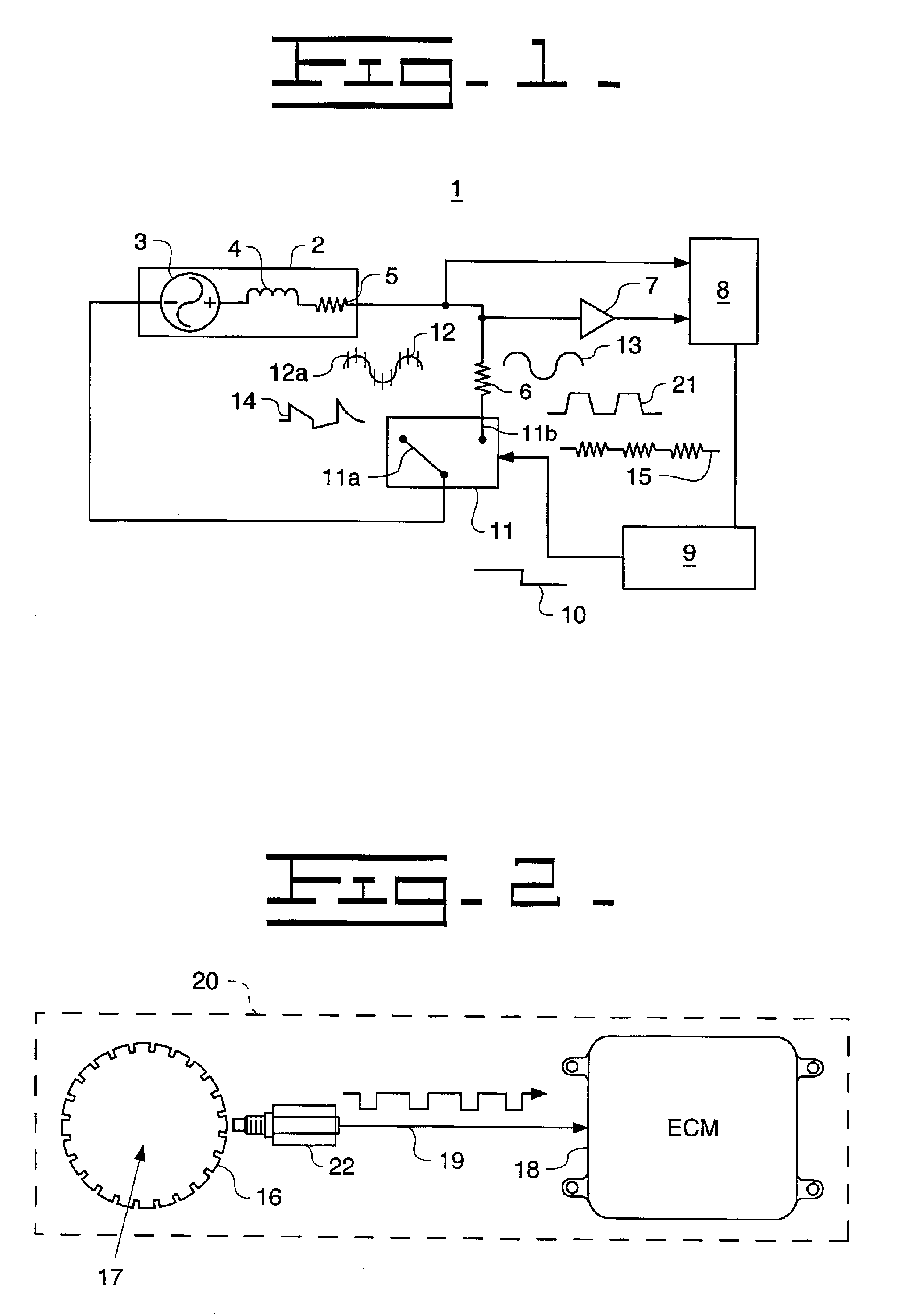
[0014]An exemplary embodiment of the present invention provides an apparatus and method of accurately sensing machine characteristics during a start-up phase of a machine and during normal operation of the machine. The following description uses a vehicle engine as an example only. As would be understood by one skilled in the art, this invention also is applicable to other types of machines having a rotating member.

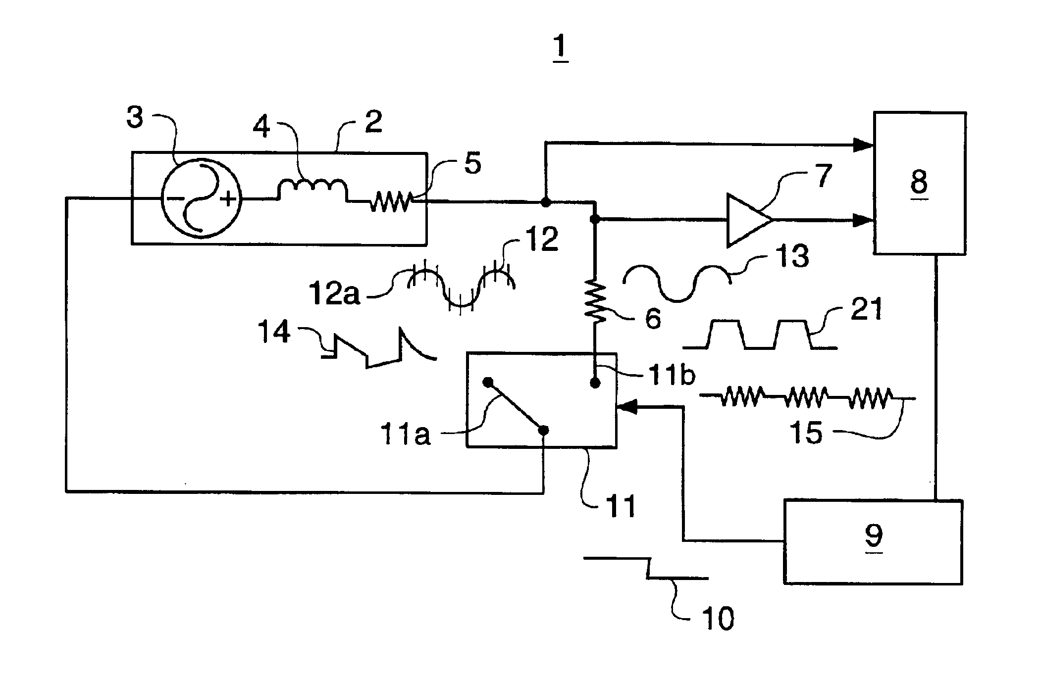
[0015]FIG. 1 illustrates a schematic diagram of an apparatus as represented by a circuit 1 that measures a characteristic of a machine. The circuit 1 may be coupled to the machine, or it may be incorporated into the machine. The circuit 1 includes a variable reluctance sensor (VRS) 2. The VRS 2 generates a basic output signal 12 having a basic frequency that is representative of the characteristic of the machine. While the VRS 2 is preferably implemented as a single fine-wire coiled about a magnetic structure (e.g., permanent magnet), the circuit 1 illustrates the VRS 2 a...


PUM


Abstract

An apparatus and method for measuring a characteristic, such as speed, of a machine. A variable reluctance sensor (VRS) is coupled to a resistive element, which filters a portion of a basic output signal generated by the VRS having a frequency above a prescribed threshold level, thus removing high-frequency noise from the basic output signal. An amplifier amplifies the filtered output signal. The filtered, amplified output signal has an increased signal-to-noise ratio such that the machine characteristic, i.e. speed, can be more accurately measured during a slow speed operation. A controller generates a control signal received by a switching device to decouple the resistive element when machine speed exceeds a prescribed threshold level. Then, the basic output signal is used to measure the characteristic of the machine during normal machine operation.

Description

TECHNICAL FIELD[0001]The present invention relates generally to a variable reluctance sensor (VRS) for use in a fuel combustion engine, and, more particularly, to a VRS that operates at low engine speed to more accurately detect gear tooth position and measure engine speed.BACKGROUND[0002]In the related art, a variable reluctance sensor (VRS) is described in U.S. Pat. No. 5,726,888, which discloses a method and system for testing a wheel speed sensor input circuit in an anti-braking system (ABS) and / or traction control (TC) system. Alternatively, a VRS, such as the VRS manufactured by Electro Corp., may be used to measure engine speed.[0003]The conventional VRS is a coil of wire wrapped around a permanent magnet, with leads for connection into a circuit. Typically, the VRS is in the form of a head that is positioned adjacent a rotatable gear or the like. Thus, when the ferrous metal of a tooth of a gear moves past the sensor head, the magnetic field is altered, and a voltage is indu...

Claims


Application Information

Patent Timeline
Patent Type & Authority Patents(United States)
IPC IPC(8): G01P3/488G01P3/42F02D41/34
CPCG01P3/488F02D41/0097
Inventor WILD, ARTHUR
Owner CATERPILLAR INC
Why Eureka
Try Eureka