
Powered soil tillage device

a soil tillage and power technology, applied in the field of powered soil tillage devices, can solve the problems of unsafe and difficult operation, inability to easily maneuver or guide rotary tillage machines obstacles or gardens, and inability to easily maneuver or guide them around or between individual plants, etc., to reduce the tendency to enangle vines and weeds, and the effect of easy operation

Active Publication Date: 2005-06-14
SUNRAY
View PDF24 Cites 44 Cited by
  • Summary
  • Abstract
  • Description
  • Claims
  • Application Information

AI Technical Summary

Benefits of technology

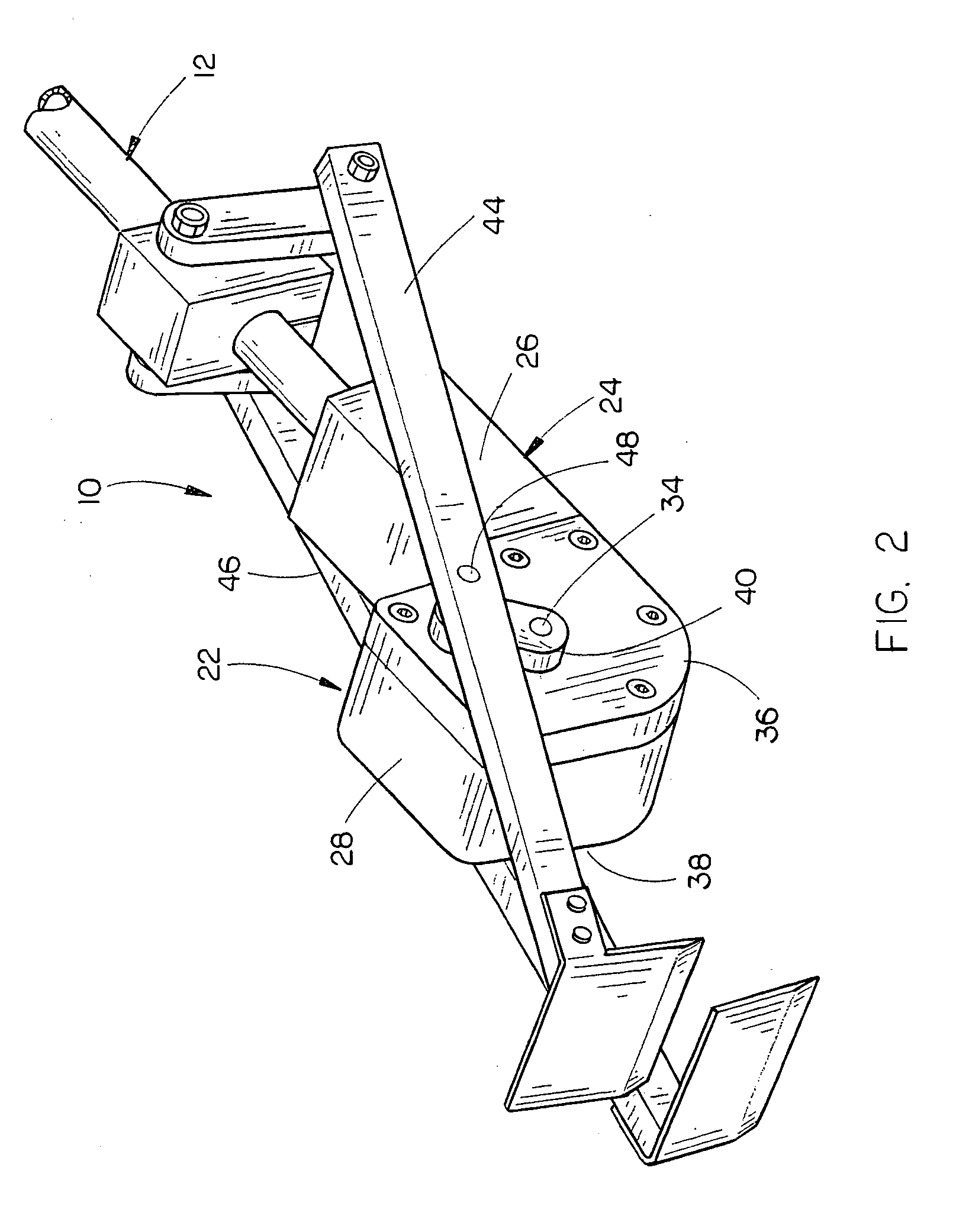
[0010]As the power means rotates the power shaft, the power shaft rotates the worm gear, which in turn rotates the spur gear to cause the first and second crank arms to rotate. As the offset crank arms rotate, one beam is moving forward and / or upward while the other beam is moving backward and / or downward such that when one blade is entering the soil, the other blade located behind it (or in front of it, depending on the machine set-up) is exiting the soil. During operation, one blade moves up and over the other blade creating a nearly constant hoeing action which minimizes impact jarring and twisting action to provide full coverage of the zone being tilled to assure severance of weed roots and the like.
[0012]Still another object of the invention is to provide a hand-held, powered soil tillage device which is lightweight and which is easily handled.
[0014]A further object of the invention is to provide a powered soil tillage device which may be either driven by an electric motor or an internal combustion engine. Still another object of the invention is to provide a powered soil tillage device wherein the ground-engaging members may comprise hoe blades, spikes, etc. A further object of the invention is to provide a powered soil tillage device which is highly maneuverable.
[0016]Still another object of the invention is to provide a powered soil tillage device which reduces the tendency to entangle vines, weeds and the like.
[0018]Still another object of the invention is to provide a powered soil tillage device which is safe to use.

Problems solved by technology

Various methods have been used for tilling or cultivating the soil, including manually operated hoes, spades, shovels, rakes and similar devices, which are labor-intensive and time-consuming.
These machines or devices are commonly known as rototillers and present safety hazards as the rotating discs, blades or tines can cause significant injury if contact occurs with the machine operator, other people, pets, etc.
The rotary motion of the tillage members can also snag and entangle clothing, which can also lead to injury.
During operation, devices of this type may lurch forward, causing unsafe and difficult operation, especially when the rotating tillage members strike plant roots, rocks or other objects, or when the soil conditions are inconsistent with hard and soft zones.
Rotary tillage machines cannot be easily maneuvered or guided around or between individual plants, obstacles or garden plot contours due to the drive wheel-like pulling or grabbing action of the rotating tillage members as they move through the soil.
As such, these machines are normally restricted to cultivating between rows of plants or where straight-line motion is possible for some distance.
Rototiller-type machines also tend to entangle weeds, vines, etc. as they snag and wrap such materials around the rotating tillage members, requiring stoppage of the machine and manual clearing of the debris.
These devices tend to be complex and in general provide limited soil cultivation effectiveness, and their use is not widespread.

Method used


Image

  • Powered soil tillage device
  • Powered soil tillage device
  • Powered soil tillage device

Examples


Embodiment Construction

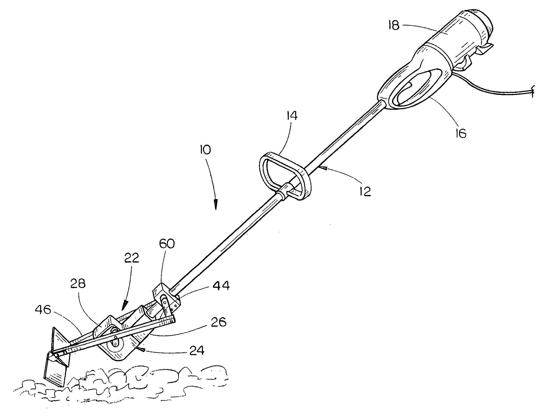
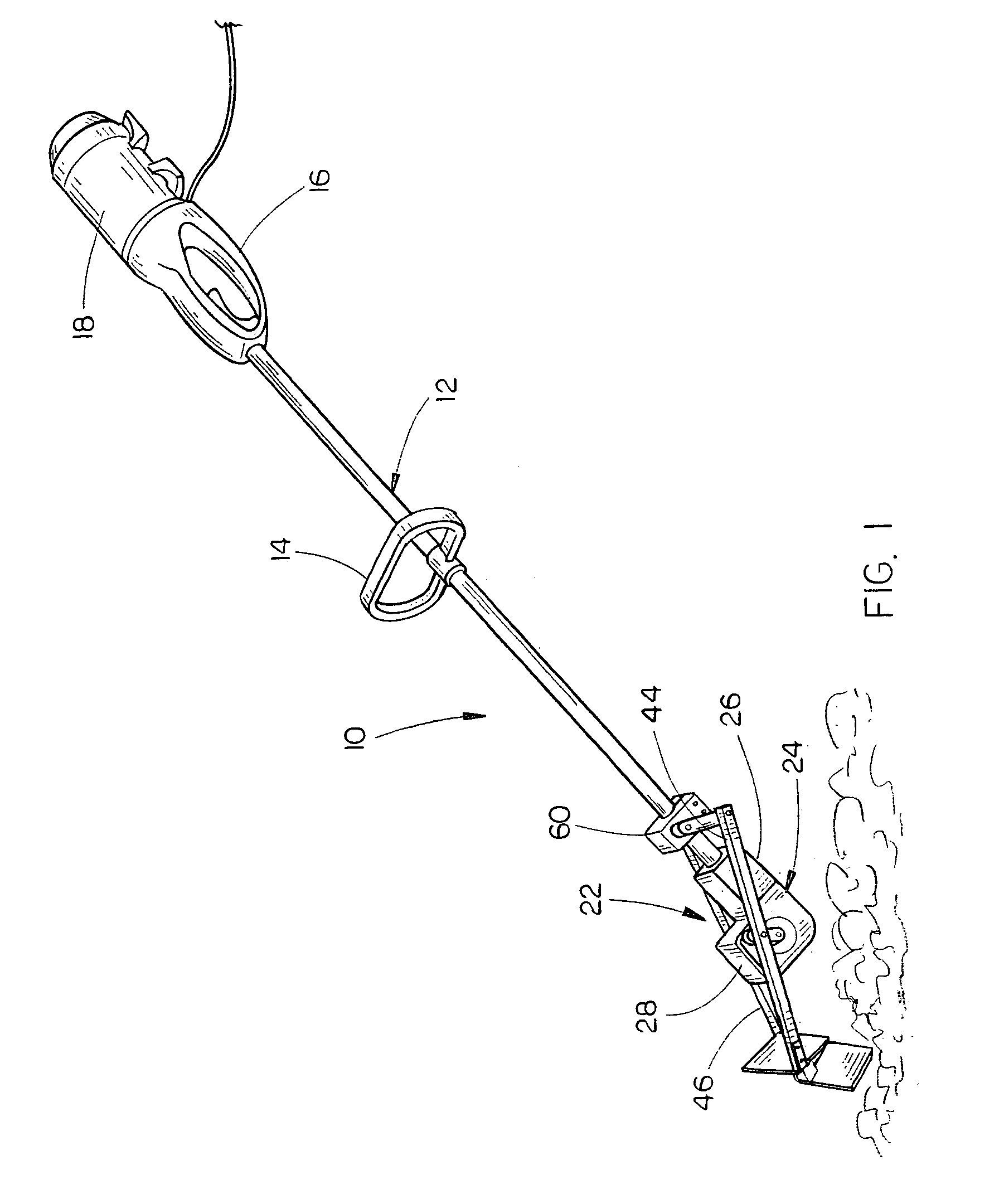
[0025]The powered soil tillage device of this invention is referred to generally by the reference numeral 10. The tillage device 10 of this invention is designed to be lightweight so as to be hand-held. The tillage device 10 includes an elongated hollow support member 12 having upper and lower ends. A handle 14 is secured to the support member 12 intermediate the ends thereof to enable a person to grasp the same with one hand. A handle 16 is secured to the upper end of the support member 12 and is of conventional design. A power means 18 is secured to the handle 16 in conventional fashion and may comprise an electric motor or an internal combustion engine. Further, the electric motor may be battery-operated if desired. The upper end of a power shaft 20, which is normally flexible, is secured to the power means and is driven thereby. The power shaft 20 extends downwardly through the interior of support member 12 to the lower end of the support member in conventional fashion. To this ...


PUM


Abstract

A powered, lightweight soil tillage device, including an elongated hollow support member having a motor and handle at the upper end thereof, and the tillage assembly mounted at the lower end thereof. The tillage assembly comprises a pair of beams which are mounted on opposite sides of a gearbox and driven thereby. The upper ends of the beams are attached to idler or rocker beams so that each of the beams is moved in a generally circular path. Hoe blades or the like are secured to the forward ends of the beams and extend inwardly therefrom so that the hoe blades are disposed one behind the other.

Description

BACKGROUND OF THE INVENTION[0001]1. Field of the Invention[0002]This invention relates to a powered soil tillage device, and more particularly to a lightweight, hand-held powered soil tillage device. More specifically, the powered soil tillage device of this invention is used to cultivate soil in preparation for seeding or planting, for loosening and aeration of soil to benefit plant development, and for the removal of weeds or unwanted vegetation in gardens, fields or similar plots.[0003]2. Description of the Related Art[0004]Various methods have been used for tilling or cultivating the soil, including manually operated hoes, spades, shovels, rakes and similar devices, which are labor-intensive and time-consuming.[0005]Various powered tillage devices employ rotary tillage members, often disc-shaped with serrated teeth or tine-like protrusions. These machines or devices are commonly known as rototillers and present safety hazards as the rotating discs, blades or tines can cause sign...

Claims


Application Information

Patent Timeline
Patent Type & Authority Patents(United States)
IPC IPC(8): A01B1/00A01B1/06
CPCA01B1/065
Inventor ZACH, LAWRENCE J.KOSCH, ALOIS J.
Owner SUNRAY
Learn More