Enclosure for outdoor equipment

Inactive Publication Date: 2005-06-14
NEC CORP
View PDF7 Cites 12 Cited by
  • Summary
  • Abstract
  • Description
  • Claims
  • Application Information

AI Technical Summary

Benefits of technology

[0015]It is therefore an object of the present invention to provide an enclosure for outdoor equipment, which can prevent the enclosure from being damaged by a rise of air pressure inside the enclosure by exhausting air from the enclosure, and further can secure safety of the enclosure and can secure easiness for fixing an inside air pressure adjusting mechanism to the enclosure and also can prevent a dew condensation from occurring in the enclosure.
[0016]According to a first aspect of the present invention, for achieving the object mentioned above, there is provided an enclosure for outdoor equipment. The enclosure for outdoor equipment provides an airtight main body in which an electronic instrument and / or an electronic circuit are disposed, and an inside air pressure adjusting mechanism in which a valve seat and a valve shaft part sitting on the valve seat in a state that a place between the valve seat and the valve shaft part can be opened and closed are disposed. And the inside air pressure adjusting mechanism is fixed to the airtight main body, and the inside air pressure adjusting mechanism prevents the atmosphere from entering the airtight main body, and exhausts air inside the airtight main body corresponding to a rise of air pressure inside the airtight main body.
[0021]According to a sixth aspect of the present invention, in the third and fourth aspects, the plate part provides a ring shape groove at the surrounding part of the hole on the rear surface of the plate, and a sealing component inserted to the ring shape groove. And the sealing component keeps air-tightness between the airtight main body and the inside air pressure adjusting mechanism.

Problems solved by technology

However, in case that the enclosure is completely airtight, the inside air pressure is raised by heat generated by its inside electronic circuit or heat conducted from the outside, and in some cases, the enclosure is damaged.
Consequently, poisonous gasses mentioned above pass between the outdoor equipment and the atmosphere, and are accumulated in the outdoor equipment.
As a result, this causes lowering the reliability of the outdoor equipment.
Further, in some cases, dust in the atmosphere is adhered to the filter, and the filter is clogged and its air pressure adjusting function is lowered.
Moreover, this filter is by no means high in its mechanical strength, in a case, this filter is broken by insects such as ants, depending on its placing position.
Consequently, its reliability in operation is lowered.
Consequently, there is a problem that the reliability is lowered in the degree of waterproof.
HEI 9-66889, a user wears the waterproof suit, therefore, the mechanism of the valve structure can not be disposed inside the waterproof suit.
That is, the mechanism of the valve structure is stuck out from the waterproof suit, and there is a possibility that the mechanism of the valve structure is damaged by a collision of users or by hitting of flowing objects caused by a storm.
Moreover, when users collide with each other, there is a possibility that the users are injured.

Method used


Image

  • Enclosure for outdoor equipment
  • Enclosure for outdoor equipment
  • Enclosure for outdoor equipment

Examples


first embodiment

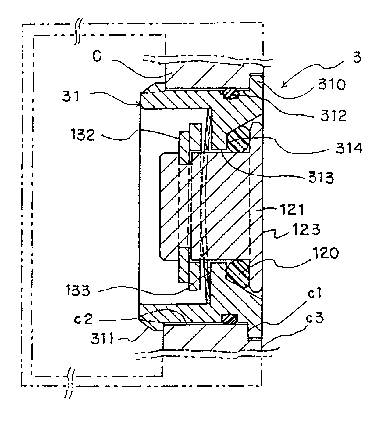
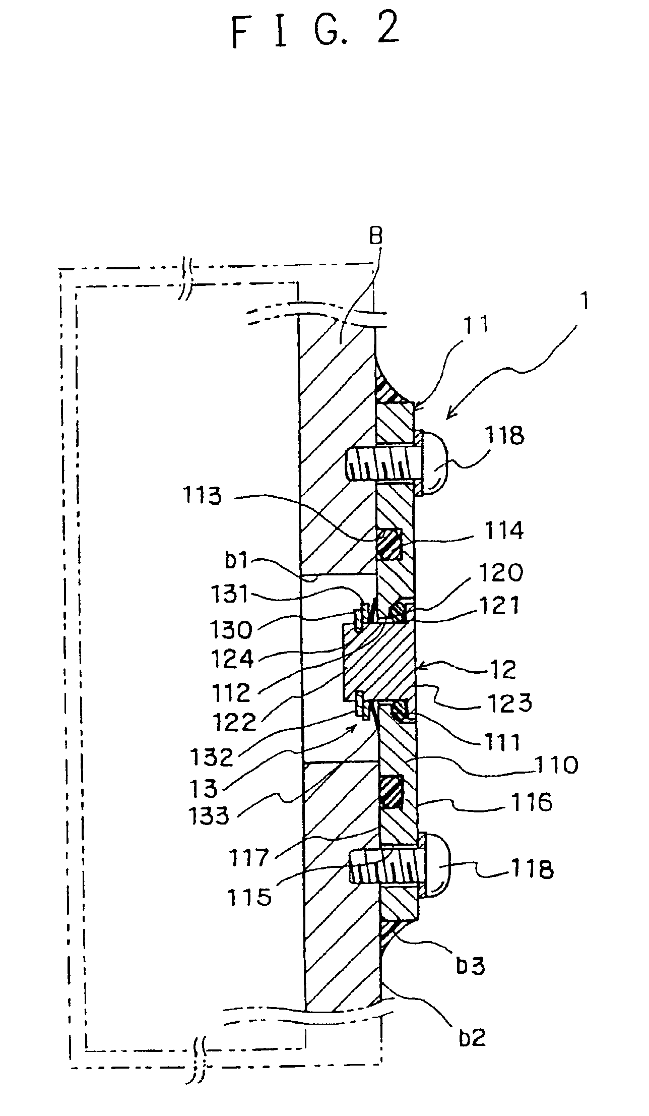
[0032]FIG. 2 is a sectional view of a part of an enclosure for outdoor equipment having an inside air pressure adjusting mechanism at the present invention. FIG. 3 is a perspective view of a part of the inside air pressure adjusting mechanism shown FIG. 2, in which components in the inside air pressure adjusting mechanism are disassembled. And FIG. 4 is sectional views of a part of the inside air pressure adjusting mechanism shown FIG. 2, in which two cases that a valve element is opened and is closed are shown.

[0033]Referring to FIGS. 2 to 4, the inside air pressure adjusting mechanism in the enclosure for outdoor equipment at the first embodiment of the present invention is explained. As shown in FIGS. 2 and 3, an inside air pressure adjusting mechanism 1 consists of a plate part 11, a valve shaft part 12, and an elastic component part 13.

[0034]In the plate part 11, a connecting hole 112, which passes through a plate 110 having a disk shape or a rectangular shape and has a valve s...

second embodiment

[0048]As shown in FIG. 5, an inside air pressure adjusting mechanism 2 in the enclosure for outdoor equipment at the present invention consists of a plate part 21, a valve shaft part 22, and an elastic component part 23.

[0049]The plate part 21 is a plate 211 whose shape is circular or rectangular. In the plate 211, a hole 212 is formed at its center, and plural ventilation holes 213 are formed at the surrounding part of the hole 212, and plural fixing holes 214 are formed at the edge of the plate 211.

[0050]The valve shaft part 22 consists of a shaft 221 and a sucker type valve 222. The sucker type valve 222 is a hat shape being curved and has flexibility, and is fixed to the shaft 221 so that the shaft 221 passes through the center of the sucker type valve 222. A ring shape groove 223 is formed at the part near the edge of the shaft 221. And the valve shaft part 22 is inserted to the hole 212 of the plate part 21 so that the sucker type valve 222 is disposed on the side of the front...


PUM


Abstract

An enclosure for outdoor equipment, which can prevent the enclosure from being damaged by a rise of air pressure inside the enclosure by exhausting air from the enclosure, and further can secure safety of the enclosure and can secure easiness for fixing an inside air pressure adjusting mechanism to the enclosure and also can prevent a dew condensation from occurring in the enclosure, is provided. The enclosure for outdoor equipment provides an inside air pressure adjusting mechanism. The inside air pressure adjusting mechanism provides a valve seat and a valve element which is seated on the valve seat in a state that the valve element can be opened and closed by placing a sealing component between them. The inside air pressure adjusting mechanism is inserted to a hole of the enclosure for outdoor equipment, in which an electronic circuit is disposed, and fixed so that the inside air pressure adjusting mechanism does not stick out largely from the front surface of the enclosure for outdoor equipment. With this, the atmosphere can be prevented from entering the enclosure and the air inside the enclosure is exhausted to the outside corresponding to a rise of the temperature inside the enclosure.

Description

BACKGROUND OF THE INVENTION[0001]The present invention relates to an enclosure for outdoor equipment, in particular, which has an inside air pressure adjusting mechanism.DESCRIPTION OF THE RELATED ART[0002]Conventionally, an enclosure having an inside air pressure adjusting mechanism, in which an inside electronic circuit is not damaged by an outside environment, has been developed. However, in case that the enclosure is completely airtight, the inside air pressure is raised by heat generated by its inside electronic circuit or heat conducted from the outside, and in some cases, the enclosure is damaged. In order to solve this problem, the enclosure has a mechanism, which exhausts air to the outside corresponding to the rise of the air pressure.[0003]FIG. 1 is a diagram showing a plan view and a sectional view of a part of a conventional enclosure having an inside air pressure adjustment mechanism. In FIG. 1 (1), the sectional view of a part of the conventional enclosure having the ...

Claims


Application Information

Patent Timeline
IPC IPC(8): H05K5/06F16K24/04H05K5/02
CPCH05K5/0213H05K5/068Y10T137/7931H05K5/0215
Inventor OYAMADA, TAKASHI
Owner NEC CORP
Why Eureka
Try Eureka