
Polyoxymethylene as structural support member and propellant

a technology of structural support and polyoxymethylene, which is applied in the direction of cosmonautic vehicles, machines/engines, explosions, etc., can solve the problems of limiting the payload weight that the vehicle is able to carry as well as its endurance, range and/or velocity, and the vehicle experiences relatively insignificant loads, etc., and achieves low coefficient of thermal conductivity, low cost, and good mechanical properties

Inactive Publication Date: 2005-06-14
PHYSICAL SCI
View PDF6 Cites 22 Cited by
  • Summary
  • Abstract
  • Description
  • Claims
  • Application Information

AI Technical Summary

Benefits of technology

"The invention is about a vehicle, a method of propelling it, and a material used in its construction. The vehicle uses a solid material made of polyoxymethylene, which is a type of plastic, as a structural support and to produce a propulsive gas. This gas is directed away from the vehicle to provide thrust and propel it. The material can also be used to reinforce other structural materials and produce clean gaseous fuels. The invention has advantages such as lightweight, multi-functional materials, increased payload capacity, and improved maneuverability. It can also provide end-of-lifetime orbital-raising capacity."

Problems solved by technology

This in turn limits the payload weight that the vehicle is able to carry as well as its endurance, range, and / or velocity.
After launch, the vehicle experiences relatively insignificant loads and much of the mass of the structural components is unnecessary, particularly for those vehicles which are expendable, non-serviceable, or non-reusable.
In those cases, the momentum associated with the structural mass constrains maneuverability and can limit mission performance.
One limitation of these past approaches is that these thermoplastic thrusters are designed for high impulse (e.g., thousands of seconds), but extremely low thrust, propulsion.
Generally, such thrusters are not suited for high thrust aerospace and underwater propulsion, which require large flows of fuel to produce the thrust.
Furthermore, combustion of fluoropolymers typically requires high pyrolysis temperatures (˜500° C.
), and results in production of soot that is unacceptable on many missions, particularly space missions involving sensitive equipment.
Combustion of polytetrafluoroethylene also tends to produce high molecular weight products that can limit propulsion performance (i.e., specific impulse).

Method used


Image

  • Polyoxymethylene as structural support member and propellant
  • Polyoxymethylene as structural support member and propellant
  • Polyoxymethylene as structural support member and propellant

Examples


example 1

Fabrication of Cylindrical Component

[0108]A cylindrical component similar to that shown in FIG. 14 was formed by machining a commercially available rod of POM material 304 to produce center bore 306 and radial slots, into which longitudinal webs of reinforcement material 308 are inserted. Examples of suitable reinforcement material include carbon cloth or fiber within an epoxy or phenolic matrix.) The resulting reinforced POM rod was then cooled to a temperature of between about −10° C. to about 0° C. to induce shrinkage. Metallic sleeve 302 was heated above ˜100° C. to induce radial thermal expansion. The POM rod was then inserted into the metallic sleeve and the assembly cured at temperatures in the range of about 100° C. to about 150° C. for over an hour to allow consolidation of reinforcement material 308 with the surrounding POM matrix. A tight mechanical force fit of the POM rod within the metallic sleeve was thus accomplished. Optionally, the bond between the POM rod and the ...

example 2

Summary of Open Burning Results

[0109]An amount of POM-A and POM-B was warmed in the presence of various oxidants to measure melting, pyrolysis, and self-ignition points.

[0110]POM-A, combined with either N2O4, NO2, or air, melted at about 175° C. Pyrolysis began at about 235° C. POM-A, combined with either N2O4 or NO2, self-ignited at around 235-275° C., and at around 350-400° C. when mixed with air. These values are in line with known values, which cite a melting point of about 175° C., a pyrolysis point of between about 200° C. and about 400° C., and a self-ignition point with air in the range of about 323-375° C.

[0111]POM-B, combined with either N2O4, NO2, or air, melted at about 165° C. Pyrolysis began at about 215° C. POM-B, combined with either N2O4 or NO2, self-ignited at around 250-275° C. POM-B, combined with air, self-ignited at a temperature greater than about 350° C.

example 3

Mass Spectrometry Data of Thermal Decomposition Products

[0112]FIG. 15 shows mass spectrometry data for products (measured in μg) produced during the thermal decomposition of POM at various temperatures. The products include carbon monoxide, formaldehyde, and other compounds (such as water or carbon dioxide) that were formed in side reactions or were initially present as impurities in the reaction materials. The presence of hydrogen was inferred from the presence of carbon monoxide. The trial runs listed as 1-3 were conducted at a temperature of ˜400 C, those listed as 5-8 were conducted at ˜500 C, those listed as 10-12 were conducted at ˜750 C, and those listed as 14-17 were conducted at ˜1000 C. The data clearly demonstrates that at temperatures of 500° C. or less, the primary fuel product is formaldehyde. For decompositions at temperatures above ˜750° C. the primary fuel products are carbon monoxide and hydrogen.


PUM

PropertyMeasurementUnit
temperaturesaaaaaaaaaa
densityaaaaaaaaaa
operating temperaturesaaaaaaaaaa

Abstract

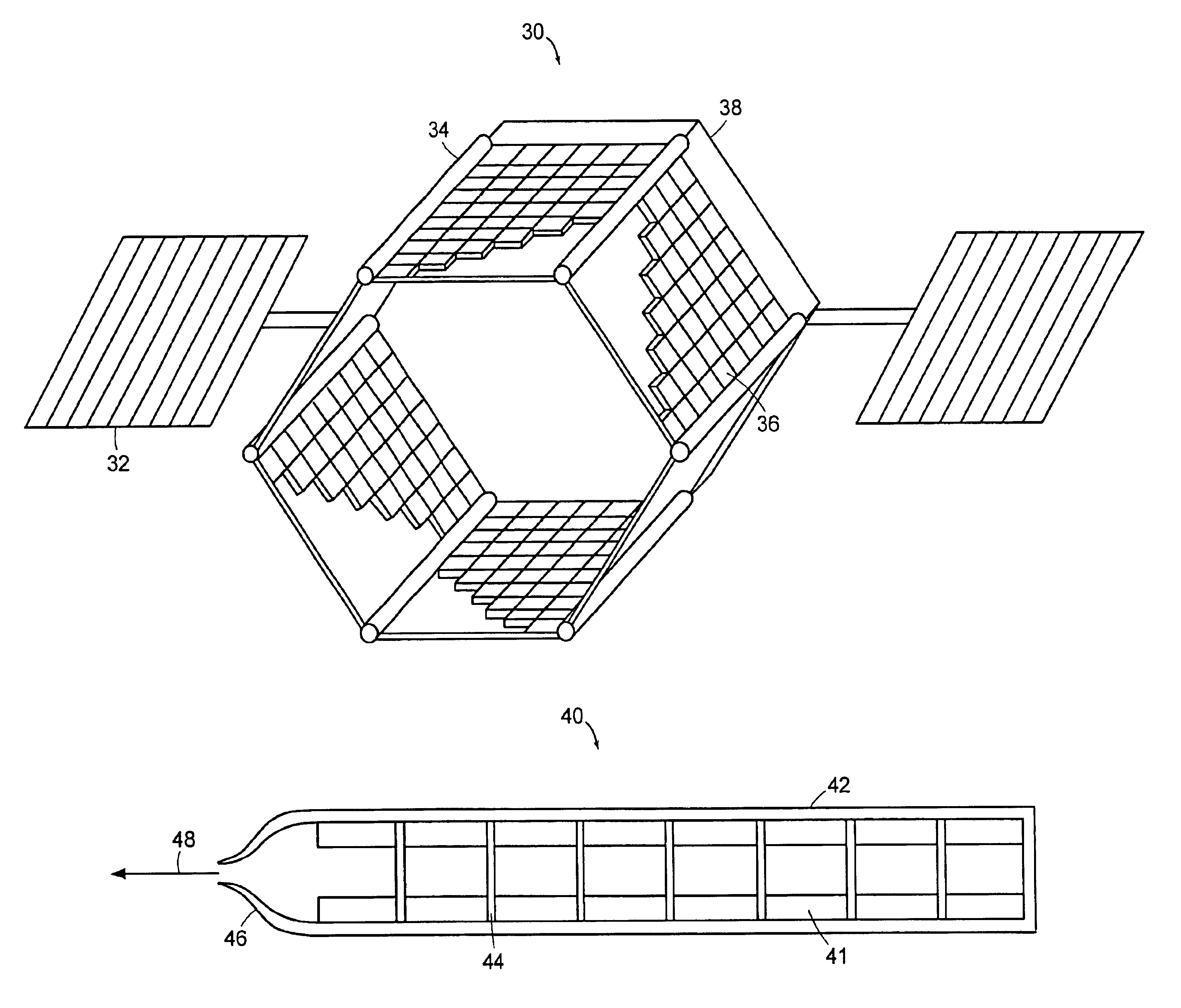
A vehicle includes at least one polyoxymethylene structural support member. The polyoxymethylene structural support member includes a polyoxymethylene component that is a propellant that provides thrust to the vehicle upon pyrolysis or combustion of the polyoxymethylene component of the product of pyrolysis of the polyoxymethylene component. The vehicle can be a satellite or other type of spacecraft.

Description

RELATED APPLICATIONS[0001]This application claims the benefit of U.S. Provisional Applications Nos. 60 / 419,897, 60 / 419,898, and 60 / 419,899 which were each filed on Oct. 18, 2002. The entire teachings of all three of those applications are incorporated herein by reference.GOVERNMENT SUPPORT[0002]Portions of this invention's development were supported under two government contracts: 1) U.S. Air Force Research Laboratory, Kirtland AFB, Contract No. F29601-99-C-0095; and 2) Defense Advanced Research Project Agency, through Office of Naval Research Contract No. N00014-00-C-0437. The Government has certain rights in the invention.BACKGROUND OF THE INVENTION[0003]Structural components in aerospace and underwater vehicle systems contain fluids or bear mechanical loads. They add mass to the vehicle, which reduces the amount of onboard propellant the vehicle is able to carry. This in turn limits the payload weight that the vehicle is able to carry as well as its endurance, range, and / or veloc...

Claims


Application Information

Patent Timeline
Patent Type & Authority Patents(United States)
IPC IPC(8): B64G1/40B64G1/42B64G1/22C06B21/00C06B31/00C06B45/10C06B45/00C06B31/28C06D5/00F02K9/08F02K9/32F02K9/00F02K9/36F42B5/16F42B5/00F42B3/02F42B3/00
CPCB64G1/22B64G1/403B64G1/421C06B21/005C06B31/28C06B45/10F02K9/08F02K9/32F02K9/36F42B3/02F42B5/16C06D5/00Y10T29/49622
Inventor JOSHI, PRAKASH B.GELB, ALAN H.UPSCHULTE, BERNARD L.GREEN, B. DAVID
Owner PHYSICAL SCI
Learn More