Groove design for precision rubber/urethane conditioning rolls

a technology of rubber/urethane and conditioning rolls, applied in mowers, agriculture tools and machines, agriculture, etc., can solve the problems of not being able to achieve the same action nor the stem cracking action of crushing rolls, and achieve excellent crushing action on crop stalks. , the effect of enhancing feeding

Inactive Publication Date: 2005-06-14
BLUE LEAF I P INC +1
View PDF22 Cites 13 Cited by
  • Summary
  • Abstract
  • Description
  • Claims
  • Application Information

AI Technical Summary

Benefits of technology

[0008]It is an object of the instant invention to provide an improved conditioner that will give enhanced feeding while maintaining an excellent crushing action to crop stalks.
[0009]It is a further object of the instant invention to provide a pair of quiet running, relatively vibrationless co-acting crop conditioning rolls having an aggressive full conditioning action.
[0010]It is a still further object of the instant invention to provide a rugged, yet economical crop conditioning roll construction.

Problems solved by technology

Crimper rolls are characterized by their aggressive feeding and stem cracking action; however, they are rough and vibrant in operation and attack the stems only at spaced intervals, leaving pockets of trapped moisture between successive transverse cracks.
In passing between the crushing rolls, the stem of a stalk is cracked open longitudinally along its full length, leaving no pockets of trapped moisture; however, neither the feeding action nor the stem cracking action of the crushing rolls is normally as aggressive as that of the crimper.

Method used


Image

  • Groove design for precision rubber/urethane conditioning rolls
  • Groove design for precision rubber/urethane conditioning rolls
  • Groove design for precision rubber/urethane conditioning rolls

Examples


Embodiment Construction

[0037]Many of the fastening, connection, processes and other means and components utilized in this invention are widely known and used in the field of the invention described, and their exact nature or type is not necessary for an understanding and use of the invention by a person skilled in the art, and they will not therefore be discussed in significant detail. Also, any reference herein to the term “left” or “right” are used as a matter of mere convenience, and are determined by standing at the rear of the machine facing in its normal direction of travel. Furthermore, the various components shown or described herein for any specific application of this invention can be varied or altered as anticipated by this invention and the practice of a specific application of any element may already by widely known or used in the art by persons skilled in the art and each will likewise not therefore be discussed in significant detail.

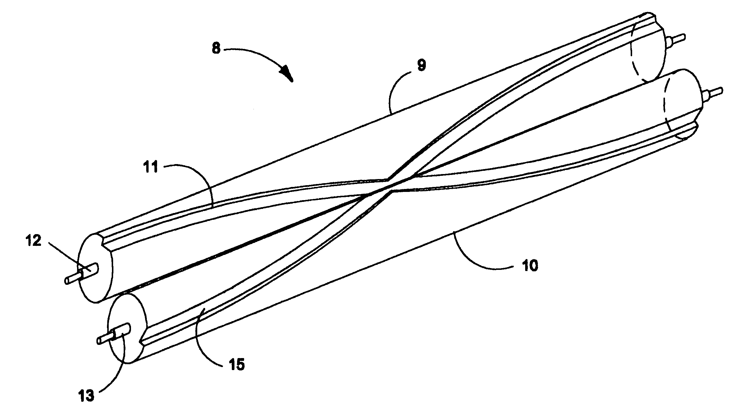
[0038]FIG. 1 shows a pair 8 of chevron-grooved, generally ...


PUM


Abstract

A conditioner roll design is provided that employs unique spiraled stepped grooves that enhance feeding of the crop mat when the rolls are abutted or at precise gaps. The groove has a leading edge and increased depth that allow expansion of the crop mat into the trailing gripper edges to provide gripping without intermeshing. The gripping side of the groove is nearly perpendicular to the direction of crop travel for positive gripping and advancing the crop. The grooves on the two rolls may be selectively timed to either mate at the point of contact or align a groove on one roll with a smooth surface on the other.

Description

[0001]This application claims benefit of U.S. Provisional Patent Application No. 60 / 468,814 filed May 8, 2003.BACKGROUND OF THE INVENTION[0002]The present invention relates generally to crop harvesting machines, commonly referred to as mower-conditioners or windrowers and, more particularly, to conditioning rolls for use in such machines.[0003]Mower-conditioners are well known in the agricultural industry, and may be found in various configurations and designs—the common functions including the severing of standing crop material from the ground, the feeding of cut crop material into a conditioner, and the depositing of the conditioned crop material onto the ground for drying. See, for example, pull-type (generally shown in U.S. Pat. No. 4,035,991), pivot tongue (generally shown in U.S. Pat. No. 5,778,647), and self-propelled (generally shown in U.S. Pat. No. 6,073,431). For purposes of providing a description of exemplary conditioner frames, torsion bars and other structure, the thr...

Claims


Application Information

Patent Timeline
Patent Type & Authority Patents(United States)
IPC IPC(8): A01D82/00A01D82/02
CPCA01D82/02Y10S56/01
Inventor PRIEPKE, EDWARD H.
Owner BLUE LEAF I P INC
Why Eureka
Try Eureka