
System and methods for correcting the injection behavior of at least one injector

a technology of injectors and injection characteristics, applied in the direction of brake systems, electric control, instruments, etc., can solve the problems of not being able to adhere to the required low tolerances, special injectors must be reworked mechanically, and the control unit and the injectors need to have a separate interfa

Inactive Publication Date: 2005-06-07
ROBERT BOSCH GMBH
View PDF8 Cites 20 Cited by
  • Summary
  • Abstract
  • Description
  • Claims
  • Application Information

AI Technical Summary

Benefits of technology

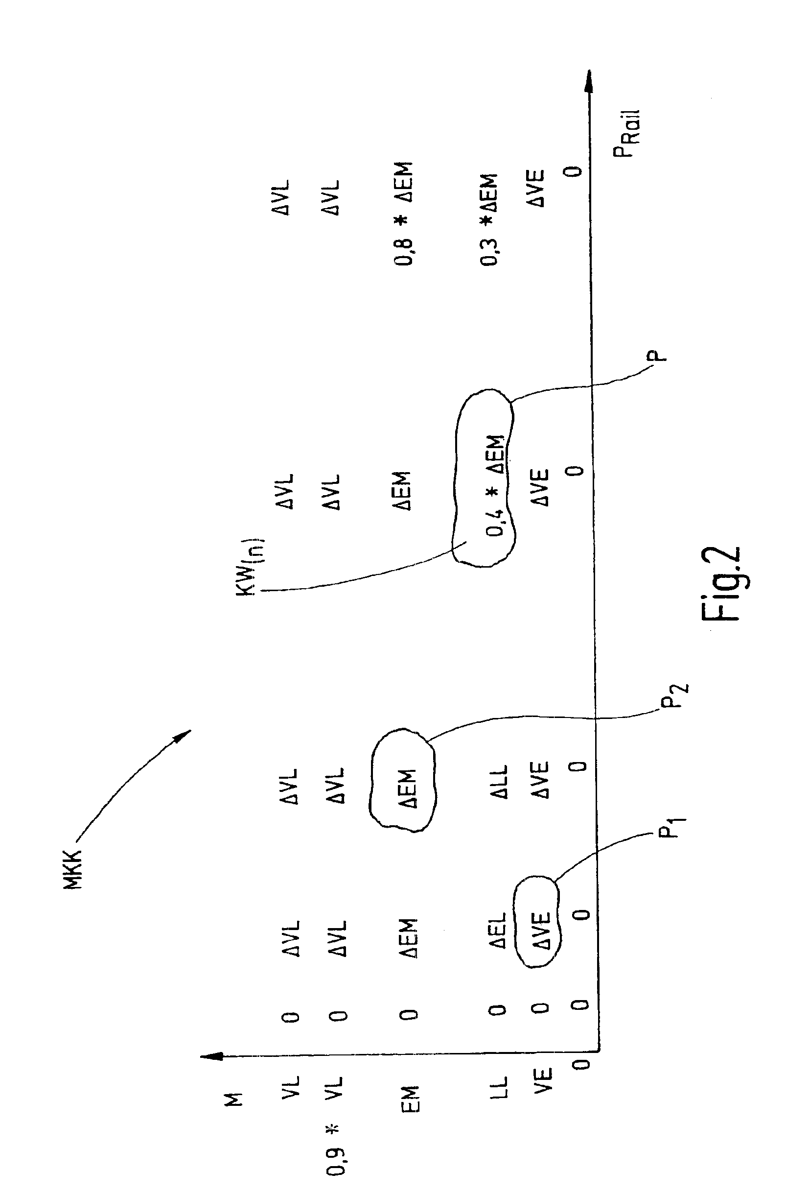
The present invention provides a system and method for controlling injectors in an engine that allows for individual control of each injector. This is possible because the system can ascertain information about each injector by comparing setpoint values to actual values, and the control unit can use this information to make corrections. This individual control can improve tolerances and increase production output. The system can also use a data memory on the injector to store the individual correction map, which can be read by the control unit for continuous processing. The method can be implemented using an integrated semiconductor circuit or an engine control unit. Overall, the system and method offer improved control accuracy and efficiency for injector control in engines.

Problems solved by technology

It is not possible to adhere to these required low tolerances because of the mechanical manufacturing tolerances.
If such a correction of the tolerances by the engine control unit is not possible based on the knowledge of the class, then the special injectors must be reworked mechanically.
However, in this design approach, it is disadvantageous that a separate interface is necessary between the control unit and the injectors.
Since only an insufficient correlation exists between the test points, a tolerance narrowing at the remaining test points is not possible.

Method used


Image

  • System and methods for correcting the injection behavior of at least one injector
  • System and methods for correcting the injection behavior of at least one injector
  • System and methods for correcting the injection behavior of at least one injector

Examples


Embodiment Construction

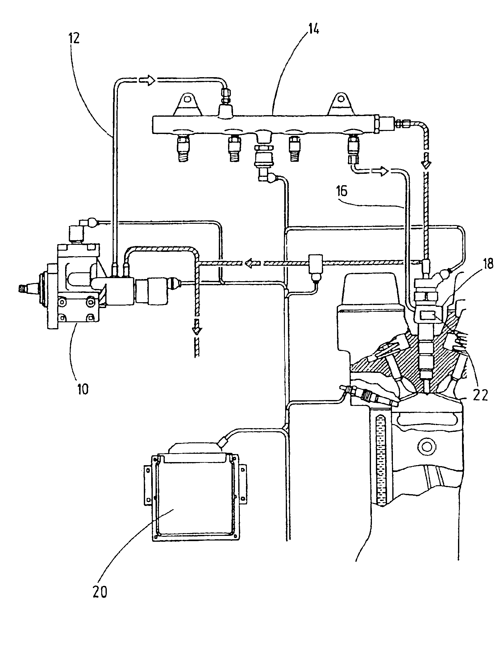
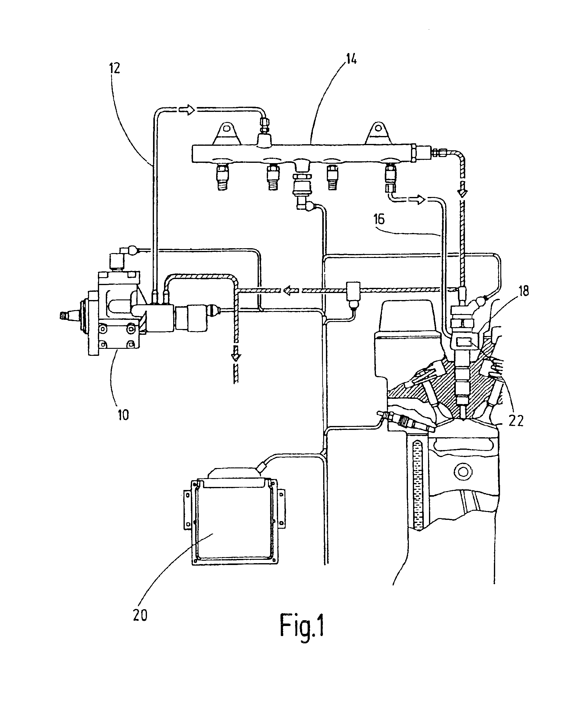
[0041]FIG. 1 shows the high-pressure stage of the common-rail fuel injection system. The configuration includes a high-pressure pump 10 connected to high-pressure accumulator (“rail”) 14 via a high-pressure delivery line 12. High-pressure accumulator 14 is connected to the injectors via further high-pressure delivery lines. One high-pressure delivery line 16 and one injector 18 are shown in the present representation. Injector 18 is installed in the engine of a motor vehicle. The system shown is controlled by an engine control unit 20. For example, injector 18 may be controlled by engine control unit 20.

[0042]A device 22 for storing information relating individually to injector 18 is provided on injector 18. The information stored in device 22 may be taken into account by engine control unit 20, so that each injector 18 may be controlled individually. The information may concern correction values for the fuel-quantity map of injector 18. Device 22 for storing information may be impl...


PUM


Abstract

A system and a method for correcting the injection characteristics of at least one injector, having a device for storing information and an arrangement for controlling the at least one injector, taking into account the stored information. The information may be ascertained by comparing setpoint values to actual values individually at a plurality of test points of at least one injector, and may be specific.

Description

FIELD OF THE INVENTION[0001]The present invention relates to a system for correcting the injection characteristics of at least one injector, having a device for storing information about the at least one injector and means for controlling the at least one injector, taking into account the stored information. The invention also relates to a method for correcting the injection characteristics of at least one injector, including the steps: storing information about the at least one injector, and controlling the at least one injector taking into account the stored information.BACKGROUND INFORMATION[0002]Electrically driven injectors for injecting fuel are used, for example, within the framework of common-rail systems. In common-rail fuel injection, pressure generation and fuel injection are decoupled. The injection pressure is generated independently of the engine speed and the injected fuel quantity, and is ready in the “rail” for the injection. The start of injection and the injected ...

Claims


Application Information

Patent Timeline
Patent Type & Authority Patents(United States)
IPC IPC(8): F02M63/02F02M61/00F02M61/16F02M65/00F02D41/00F02M63/00F02D41/24F02D41/38F02D41/32F02D45/00
CPCF02D41/2416F02D41/2432F02D41/2467F02D41/28F02M65/00F02M61/16F02M63/0225F02D41/2435F02D2041/2055F02D2400/18F02D41/3809F02D41/30
Inventor KUEGEL, PETERVEIT, GUENTERKLOPPENBURG, ERNST
Owner ROBERT BOSCH GMBH
Learn More