
System and method for inverting automatic gain control (AGC) and soft limiting

Inactive Publication Date: 2005-06-07
BLACKBERRY LTD
View PDF9 Cites 16 Cited by
  • Summary
  • Abstract
  • Description
  • Claims
  • Application Information

AI Technical Summary

Benefits of technology

[0010]According to an aspect of the invention, a signal receiver comprises a primary signal processor comprising a signal input configured to receive an input signal having a first signal dynamic range, an intermediate signal output configured to provide a scaled signal representative of the input signal, a primary variable-gain amplifier coupled to the signal input and the intermediate signal output, and a primary gain controller coupled to the primary amplifier and configured to control a gain applied by the primary amplifier to maintain the scaled signal within a second signal dynamic range, and a secondary signal processor comprising a signal input coupled to the intermediate signal output, a final signal output configured to provide an output signal representative of the input signal, a secondary variable-gain amplifier coupled to the intermediate signal output and the final output, and a secondary gain controller coupled to the secondary amplifier and configured to control a gain of the secondary amplifier to set the gain of the secondary amplifier to a first gain value when a parameter associated with the scaled signal exceeds a threshold value, and to set the gain of the secondary amplifier to a second gain value different from the first gain value when the signal parameter is less than the threshold value.
[0011]A signal receiver according to a further aspect of the invention comprises a primary signal processor comprising a signal input configured to receive an input signal having a first signal dynamic range, an intermediate signal output configured to provide a scaled signal representative of the input signal, a primary variable-gain amplifier coupled to the signal input and the intermediate signal output, and a primary gain controller coupled to the primary amplifier and configured to control a gain applied by the primary amplifier to maintain the scaled signal within a second signal dynamic range, a secondary signal processor comprising a signal input coupled to the intermediate signal output, a final signal output configured to provide an output signal representative of the input signal, a first secondary variable-gain amplifier having an input coupled to the intermediate output and an output configured to provide a full dynamic range output signal having the first signal dynamic range, a second secondary variable-gain amplifier coupled to the output of the first secondary amplifier and the final output, and a secondary gain controller coupled to the secondary amplifier and comprising a first gain control output configured to control a gain of the first secondary amplifier to set a gain of the first secondary amplifier to an inverse of the gain of the primary amplifier, and a second gain control output configured to control a gain of the second secondary amplifier to set the gain of the second secondary amplifier to a first gain value when a signal parameter of the scaled signal exceeds a threshold value, and to set the gain of the secondary amplifier to a second gain value different from the first gain value when the signal parameter is less than the threshold value.
[0012]In a signal receiver, a method for processing a signal according to an embodiment of the invention comprises the steps of receiving an input signal having a first signal dynamic range, applying a first controlled gain to the input signal to provide a scaled signal representative of the input signal, controlling the first controlled gain to maintain the scaled signal within a second signal dynamic range, applying a s

Problems solved by technology

Wireless communication systems are often vulnerable to fading and other effects, which may cause the amplitude of received signals to vary.
Unfortunately, the use of high resolution ADCs increase the manufacturing cost and power consumption of the receiver.
However, soft decision processing arrangements, which can improve the performance of some receivers, cannot be easily implemented with AGC.

Method used


Image

  • System and method for inverting automatic gain control (AGC) and soft limiting
  • System and method for inverting automatic gain control (AGC) and soft limiting
  • System and method for inverting automatic gain control (AGC) and soft limiting

Examples


Embodiment Construction

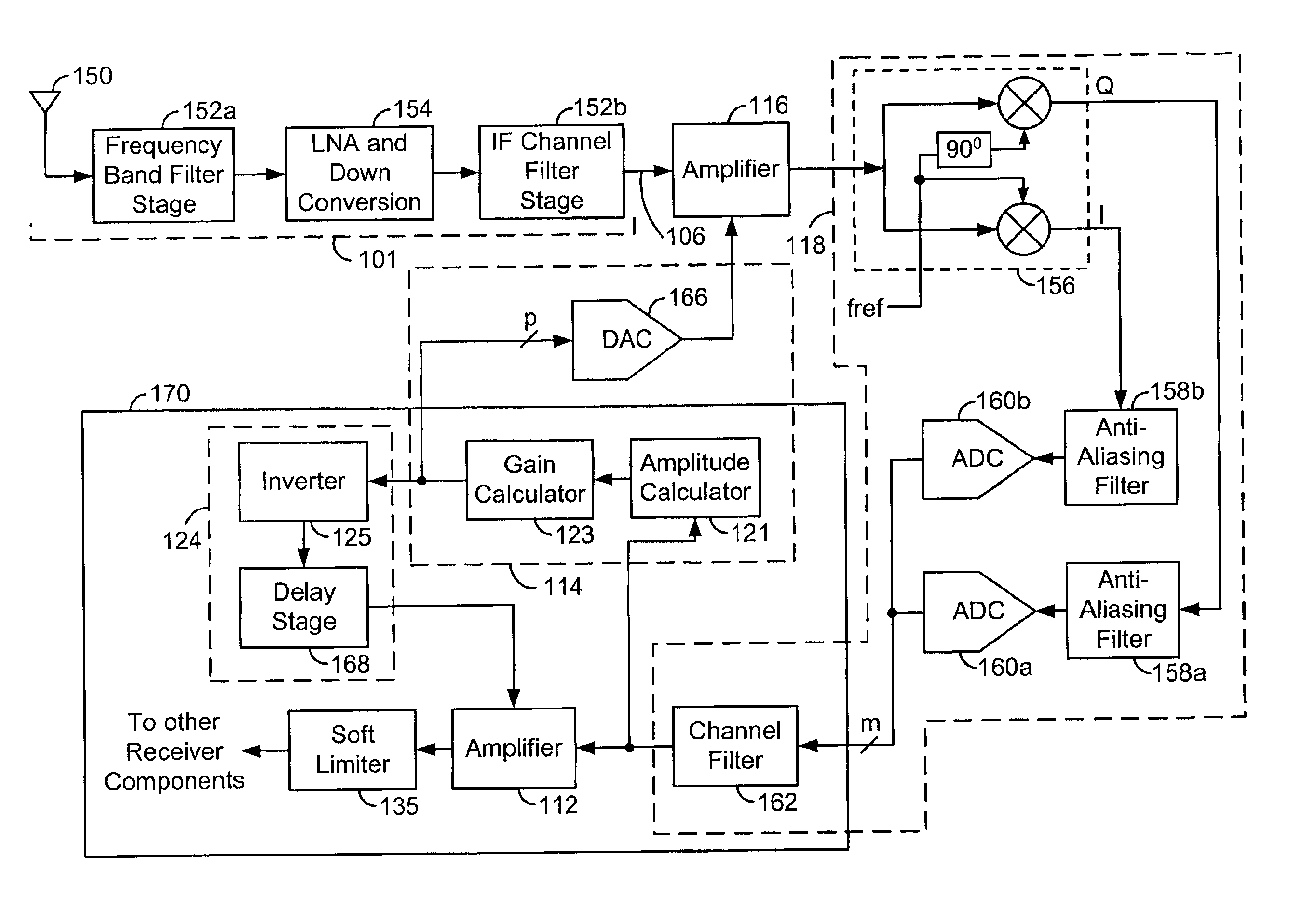
[0026]Turning to FIG. 1, a signal receiver, denoted generally as 100, is shown comprising a receiver front end 101, a primary signal processor 102 connected to the receiver front end 101, and a secondary signal processor 104 coupled to the primary signal processor 102. The receiver front end 101 may include an antenna, one or more filters, a frequency converter, and such other components as would typically be found in a communication signal receiver. The primary signal processor 102 includes a signal input 106 for receiving an input signal thereon, a signal output 108 for providing an output signal representative of the input signal, an amplifier 116 coupled to the signal input 106, a signal converter 118 connected to the output of the amplifier 116 and the signal output 108, and a primary gain controller 114 coupled to the output 108 and the amplifier 116.

[0027]The amplifier 116 is preferably a variable-gain analog signal amplifier, and has an analog signal input connected to the s...


PUM


Abstract

A soft limiter for a signal processor includes a variable-gain amplifier, and a threshold detector. The variable-gain amplifier includes a signal input for receiving an input signal, a signal output for providing an output signal representative of the input signal, and a gain control input for controlling a gain of the amplifier. The threshold detector is coupled to the gain control input, and includes a control input for receiving a control variable thereon. The threshold detector is configured to set the gain of the amplifier to a first gain value when the control variable exceeds a threshold value, and to set the gain to a second gain value different from the first gain value when the control variable is less than the threshold value.

Description

CROSS-REFERENCE TO RELATED APPLICATION[0001]This application claims priority from U.S. Provisional Application Ser. No. 60 / 252,794, filed on Nov. 21, 2000. The complete disclosure of this provisional application, including drawings, is hereby incorporated into this application by reference.FIELD OF THE INVENTION[0002]The present invention relates to gain control in communication signal receivers. In particular, the present invention relates to a receiver having a variable-gain amplifier and operable in an environment where input signal level has a large dynamic range.BACKGROUND OF THE INVENTION[0003]Wireless communication systems are often vulnerable to fading and other effects, which may cause the amplitude of received signals to vary. Consequently many wireless receivers employ automatic gain control (AGC) circuits which attempt maintain an output scaled signal at a substantially constant amplitude or power level, despite variations in a received signal.[0004]Conventional AGC circ...

Claims


Application Information

Patent Timeline
IPC IPC(8): H03G11/00H03G7/00H03G11/04H03G7/06H03G3/20H04B1/18H04W88/02
CPCH03G11/04H03G7/06
Inventor SIMMONS, SEAN B.KEMENCZY, ZOLTAN
Owner BLACKBERRY LTD
Learn More