
Anti-copying system for audio signals

an anti-copying and audio signal technology, applied in the field of anti-copying systems for audio signals, can solve the problems of many illegal copies of cds or other information carriers, substantial loss of copyright royalties,

Inactive Publication Date: 2005-06-07
SPIRO J PANDELIDIS HIGH TECH APPL
View PDF7 Cites 26 Cited by
  • Summary
  • Abstract
  • Description
  • Claims
  • Application Information

AI Technical Summary

Benefits of technology

[0003]It is an object of the present invention to provide a method for protecting audio signals against unauthorized copying.
[0004]Accordingly, the present invention provides a method of protecting an audio signal against copying, the method comprising the step of mixing the audio signal with at least one non-audible disturbance signal.
[0005]By mixing the audio signal with a non-audible disturbance signal, that is an additional signal having a frequency lying outside the normal audible range, it is possible to obtain a combined audio signal which is, when replayed as it is, effectively undisturbed but which shows audible disturbances when copied.
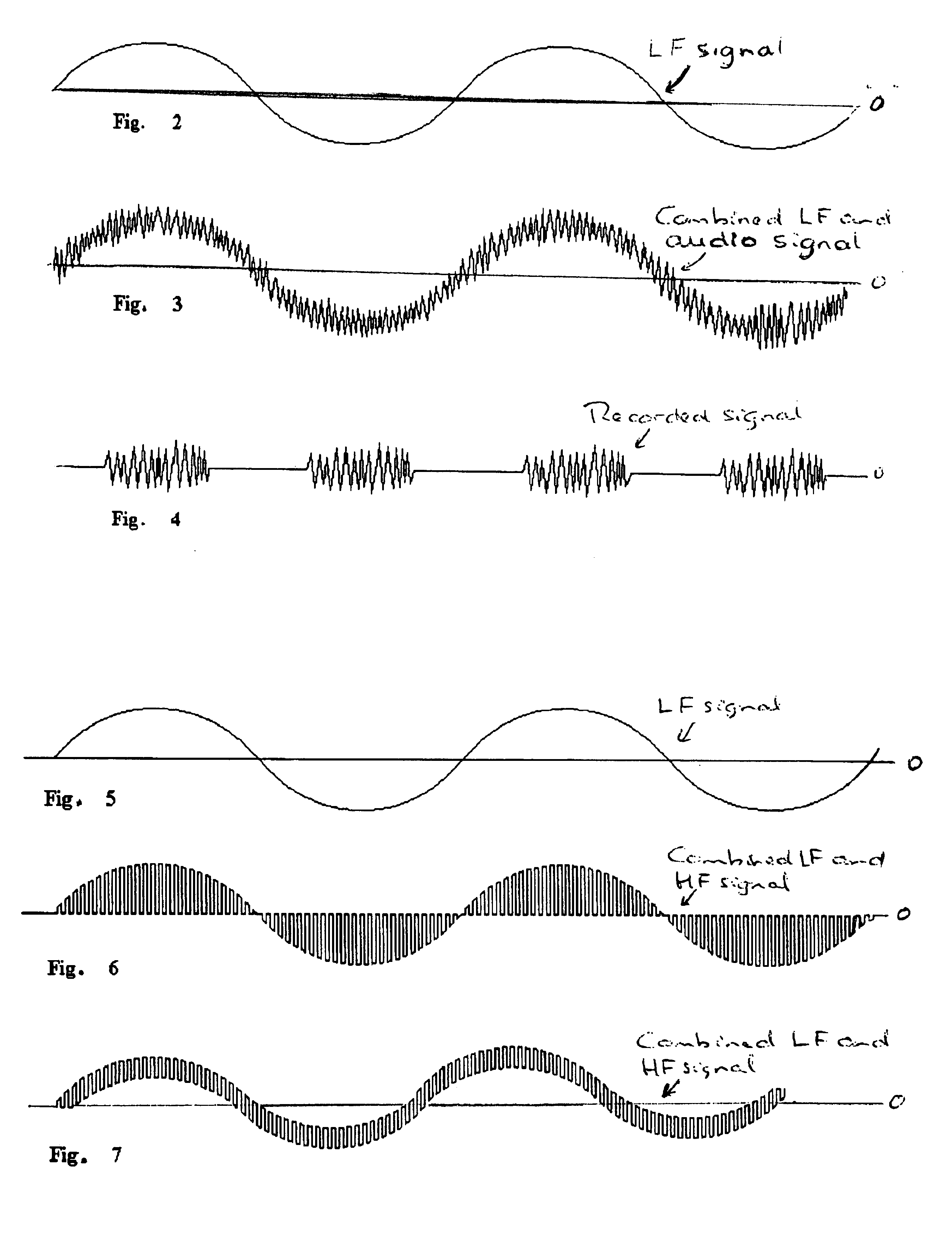
[0006]Advantageously, a first disturbance signal is a low-frequency signal which is added to the audio signal. When the original audio signal and the low-frequency first disturbance signal have comparable amplitudes, the resulting mixed output signal will be highly resistant against copying to an analogue tape recorder. This aspect of the present invention is based on the insight that slowly varying signals cause the magnetic heads of a tape recorder to effectively erase the recorded signal, or at least to suppress the recording of the signal.
[0008]Advantageously, a second disturbance signal is a high-frequency signal which is multiplied with the audio signal. This may effectively result in the original audio signal being substantially interrupted (“chopped”) at a high interruption frequency. Although this regular interruption is normally not audible due to the high (non-audible) frequency involved, copying of the signal will result in an incomplete demodulation of the combined signal due to the characteristics of the copying devices.

Problems solved by technology

The possibility of digital copying, producing perfect copies of the original, has resulted in many illegal copies of CDs or other information carriers being made.
This in turn leads to a substantial loss in copyright royalties.

Method used


Image

  • Anti-copying system for audio signals
  • Anti-copying system for audio signals
  • Anti-copying system for audio signals

Examples


Embodiment Construction

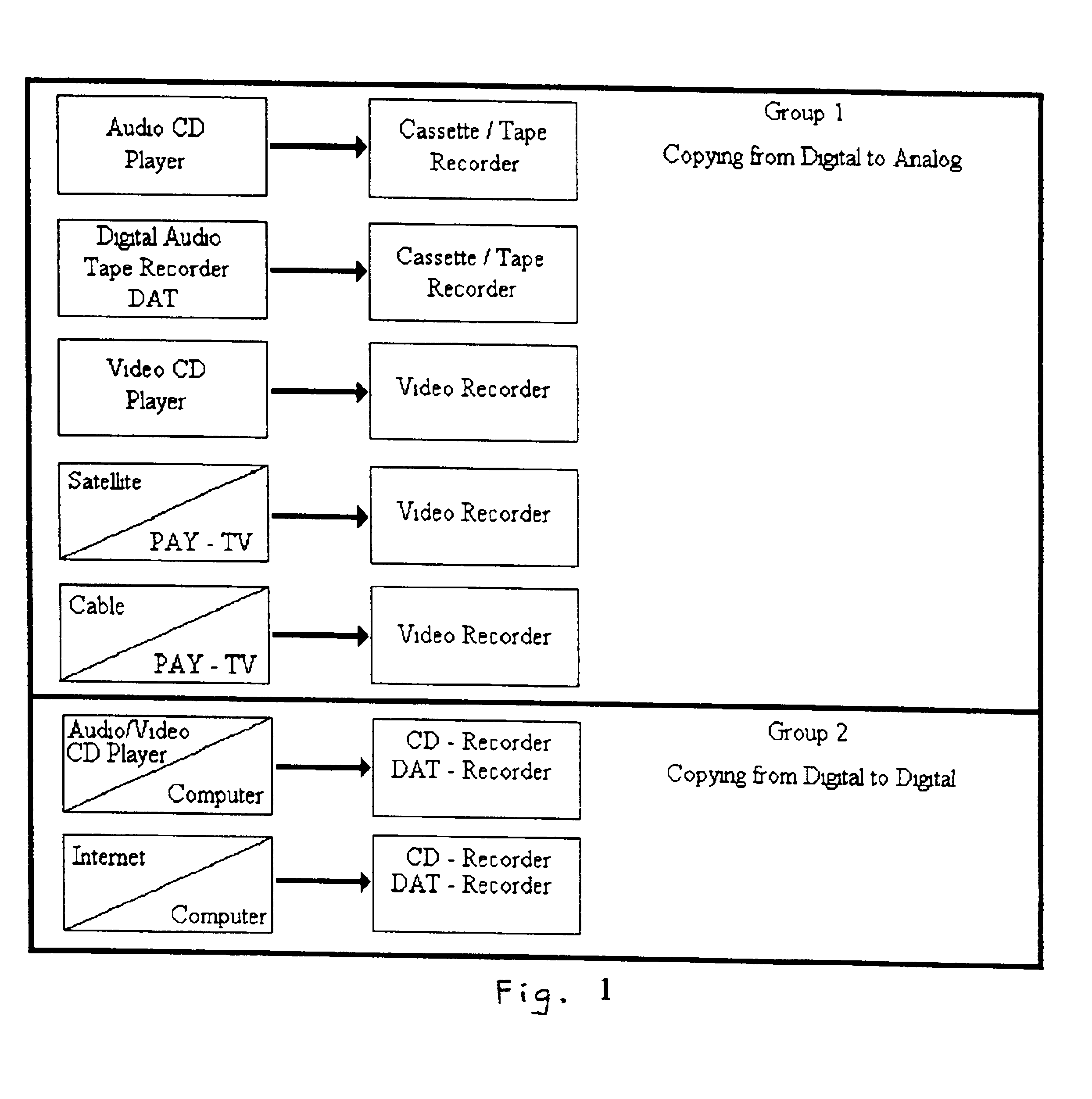
[0027]As shown in FIG. 1, the copying of (digital) audio signals may be considered to involve two categories or groups of copying operations:[0028]Group 1: from digital to analog signals, and[0029]Group 2: from digital to digital signals.

Although some of the techniques described in this document may also apply to copying from analog to analog signals (signal representations), the following discussion will focus on the copying of digital audio signals, that is audio signals registered in a digital representation (sampled audio signals represented digitally by ones and zeros).

[0030]Especially group 2 poses problems with respect to copyright, as the CD-burners and DAT-recorders normally allow perfect copies of the original signals to be made (it will be understood that so-called DAT-recorders are tape / cassette recorders which digitally register audio signals on tape).

[0031]According to a first aspect of the present invention, a low-frequency disturbance signal (also called first distur...


PUM

PropertyMeasurementUnit
frequencyaaaaaaaaaa
frequencyaaaaaaaaaa
frequencyaaaaaaaaaa

Abstract

In order to protect audio signals against copying, it is proposed to mix the audio signal with at least one non-audible disturbance signal. A first disturbance signal may be a low-frequency signal which is added to the audio signal, while a second disturbance signal may be a high-frequency disturbance signal which is multiplied with the audio signal. Additionally, the second disturbance signal may be modulated by a modulating signal comprising either the original or inverted original signal, or spoken messages indicative of an illegal copy.

Description

BACKGROUND OF THE INVENTION[0001]The present invention relates to an anti-copying system for audio signals, in particular digital audio signals.[0002]Present day digital techniques allow perfect copies of audio signals to be made. For example, the digital audio information of a compact disc (CD) can be digitally registered on tape or can even be used to physically reproduce the CD by means of a so-called CD burner (recorder for compact discs). The possibility of digital copying, producing perfect copies of the original, has resulted in many illegal copies of CDs or other information carriers being made. This in turn leads to a substantial loss in copyright royalties. For this reason, there is a need for protection against copying of audio signals.SUMMARY OF THE INVENTION[0003]It is an object of the present invention to provide a method for protecting audio signals against unauthorized copying.[0004]Accordingly, the present invention provides a method of protecting an audio signal ag...

Claims


Application Information

Patent Timeline
Patent Type & Authority Patents(United States)
IPC IPC(8): G11B20/00H04H1/00G11B20/10G11B20/12H04H20/31H04H60/18
CPCG11B20/00086G11B20/00891H04H60/18H04H20/31G11B20/00927
Inventor WIJNEN, ARIE M.PANDELIDIS, SPIRO J.
Owner SPIRO J PANDELIDIS HIGH TECH APPL
Learn More