Detection of defects embedded in servo pattern on stamper by using scattered light

a technology of scattered light and servo pattern, applied in the field of disk drives, can solve problems such as physical defects, offsets in scattered beams, and unexpected kerr rotation

Inactive Publication Date: 2005-06-07
SEAGATE TECH LLC
View PDF3 Cites 7 Cited by
  • Summary
  • Abstract
  • Description
  • Claims
  • Application Information

AI Technical Summary

Problems solved by technology

The defects may be physical defects, magnetic defects or both.
Physical defects cause offsets in the scattered beam.
Magnetic defects cause unexpected Kerr rotation.

Method used


Image

  • Detection of defects embedded in servo pattern on stamper by using scattered light
  • Detection of defects embedded in servo pattern on stamper by using scattered light
  • Detection of defects embedded in servo pattern on stamper by using scattered light

Examples


Embodiment Construction

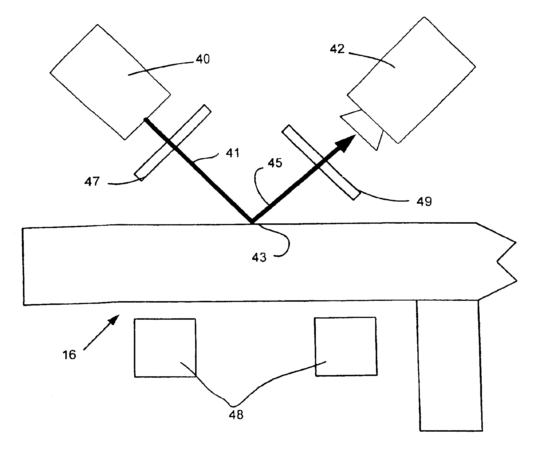
[0024]FIG. 3 illustrates an apparatus for detecting physical defects on a hard disk servo pattern stamper. In the Fig., stamper 16 has embossed on at least one surface thereof a servo pattern consisting of raised surfaces 17. The servo pattern may have physical defects. A first kind of physical defect is a dropout 34. A dropout consists of a missing embossed pattern, i.e., an empty space appears where the servo pattern would call for stamper to have an embossed raised feature. This is illustrated by the dotted line 34 in the figure indicating the absence of embossed feature. This is a dropout.

[0025]The second kind of physical defect is debris 36. Debris 36 may be lodged onto the stamper 16 in area of the servo pattern 17. Debris not only causes the false recording of a servo “pattern” on the magnetic hard disk, the debris may cause physical damage to the disk.

[0026]Referring again to FIG. 3, a light source 30 emits a beam of light 31 which reflected by the stamper at point 33, for e...


PUM

PropertyMeasurementUnit
lengthaaaaaaaaaa
lengthaaaaaaaaaa
lengthaaaaaaaaaa

Abstract

Defects of a hard disk drive servo pattern stamper are detected by comparing a scattered light beam pattern against the known servo pattern. A magnetic field is applied to stamper and the beam is linearly polarized. Variations in the physical offset of the beam, its scatter, are indicative of physical defects. Variations in the Kerr rotation of scattered beam are indicative of magnetic defects.

Description

CROSS-REFERENCE TO RELATED APPLICATIONS[0001]This application claims benefit of U.S. provisional patent application Ser. No. 60 / 392,788, filed on Jun. 28, 2002, which is hereby incorporated by reference.BACKGROUND OF THE INVENTION[0002]1. Field of the Invention[0003]The invention relates to field of disk drives and more particularly to methods for writing servo tracks on magnetic hard disks.[0004]2. Description of Related Art[0005]Hard disk drives provide prerecorded tracking servo information on the data recording surfaces of their magnetic hard disks. This servo information typically comprises servo bursts spaced evenly along tracks. Data is recorded between the servo bursts. In most cases, servo bursts are approximately radially aligned, describing a small arc from the disk's ID to its OD. This radial alignment makes them look like arced spokes of the wheel. They are made to form and arc because the servo data is read by a rotary actuator that describes the same arc because the t...

Claims


Application Information

Patent Timeline
Patent Type & Authority Patents(United States)
IPC IPC(8): G11B27/36G11B5/82
CPCB82Y10/00G11B5/743G11B27/36G11B5/82G11B2220/20
Inventor LEIGH, JOSEPHKURATAKA, NOBUO
Owner SEAGATE TECH LLC
Why Eureka
Try Eureka