
Item finding using RF signalling

a technology of rf signalling and object identification, applied in the direction of using reradiation, burglar alarm mechanical actuation, instruments, etc., can solve the problem of wasting time and effort, limiting the physical scanning and location of bar code labels at close range by a bar code reader, and wasting time and energy

Active Publication Date: 2006-11-28
SYMBOL TECH LLC
View PDF7 Cites 102 Cited by
  • Summary
  • Abstract
  • Description
  • Claims
  • Application Information

AI Technical Summary

Benefits of technology

The patent describes an apparatus and method for locating a specific item among many others using a portable communication system with a directional antenna. The system interrogates the items and receives unique identifiers from the RFID tags attached to them. The identifiers are then compared with a stored unique identifier for the specific item, and the apparatus indicates the relative proximity and angle of bearing of the item. The method also sends a signal to the user when a new item is identified, and the process is repeated for different locations of the interrogator. The technical effect of this invention is to provide a convenient and efficient way to locate specific items among many others using RFID technology.

Problems solved by technology

When there are many packages or items that are similar in appearance this can be a daunting and very time consuming task.
The advent of bar-code identification has somewhat simplified such tasks, but suffers from the limitation that each bar code label must be located and physically scanned at close range by a bar code reader.
This can be extremely time consuming and inefficient.
However, not all package or item storage locations have such infrastructure.

Method used


Image

  • Item finding using RF signalling
  • Item finding using RF signalling
  • Item finding using RF signalling

Examples


Embodiment Construction

[0013]The following detailed description is merely exemplary in nature and is not intended to limit the invention or the application and uses of the invention. Furthermore, there is no intention to be bound by any expressed or implied theory presented in the preceding technical field, background, brief summary or the following detailed description.

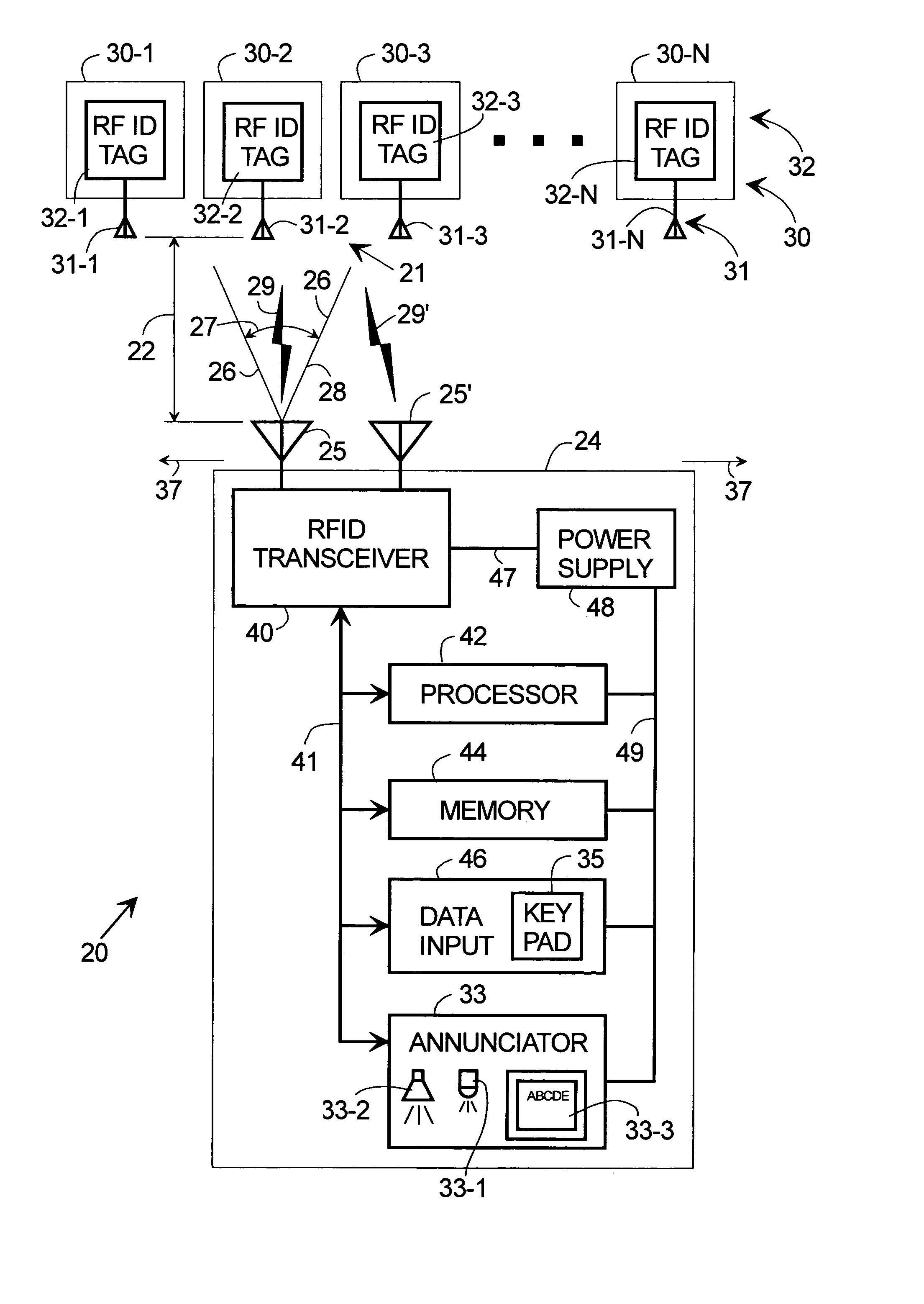
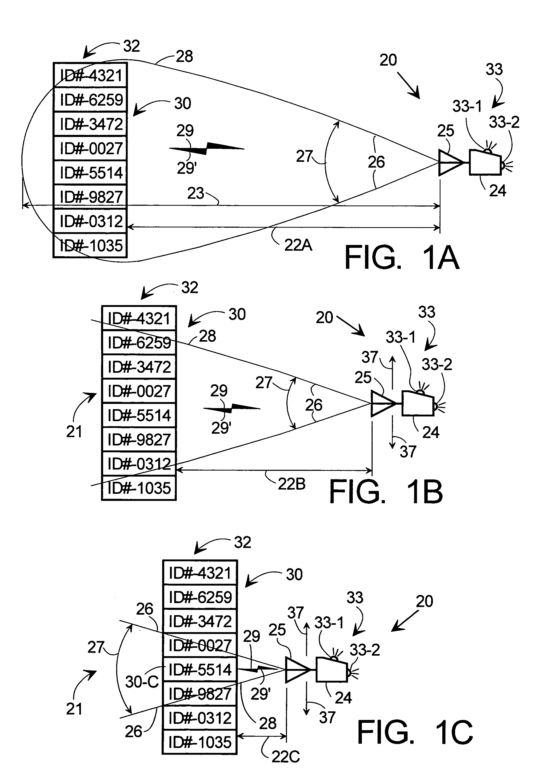
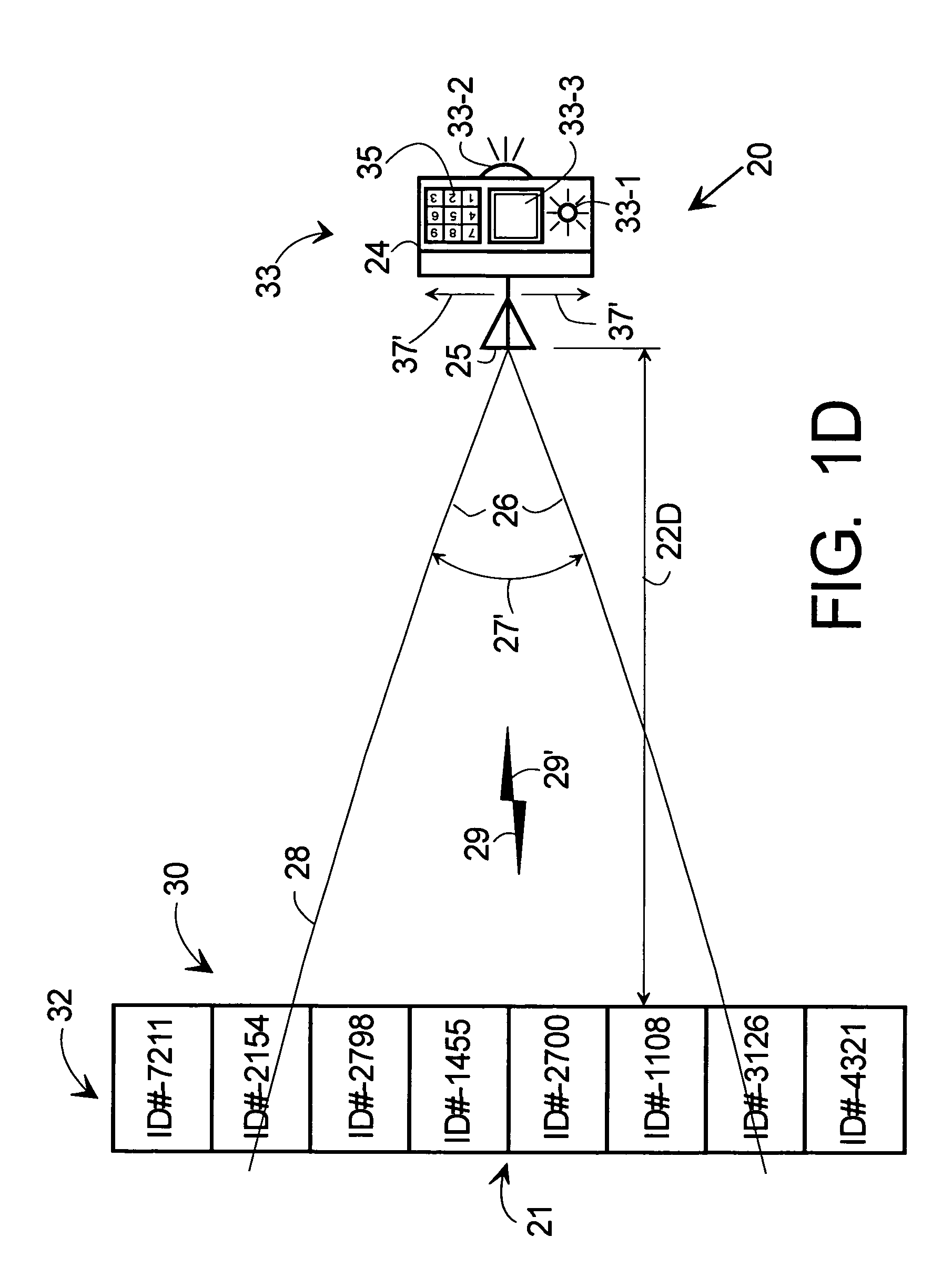
[0014]FIGS. 1A–C are simplified side views of item identification and locator system 20 of the present invention, interacting with items 30 having thereon RFID tags 32, for three different locator-item separations 22A, 22B, 22C. FIG. 1D is a plan or top view of system 20 interacting with the same items and tags at locator-item separation 22D. Persons of skill in the art will understand that FIGS. 1A–C are two dimensional side views and FIG. 1D is a two-dimensional top view of, in this example, a three-dimensional pile of objects or items 30 and associated RFID tags 32. System 20 comprises RF interrogator 24 with associated antenna 25 and a...


PUM


Abstract

Methods and apparatus are provided for locating one among many items equipped with RFID tags. The apparatus comprises a portable system interrogating the RFID tags and receiving responses therefrom that depend at least on their bearing angle. A comparator selects responses from the one item and ignores others. An annunciator indicates the presence of the one item in the interrogator field of view and, desirably but not essentially, its relative proximity. A directional antenna whose beam pattern is limited in azimuth and / or elevation provides bearing angle information. Its field of view becomes progressively smaller as the antenna approaches the one item so that a user can substantially pinpoint its location without needing any of the usual RFID infrastructure. Tag response hit rate and / or signal strength provides range related information to the interrogator. Optionally, the presence of each new tag is announced until all new tags have been identified.

Description

TECHNICAL FIELD[0001]The present invention generally relates to remotely identifying and locating objects, and more particularly relates to remotely identifying and locating objects using RF signaling.BACKGROUND[0002]There are many applications today where it is desired to sense the presence and location of a specific object, as for example, a package stored in a warehouse or on a pallet or in a shipping container. For example, a warehouse attendant or shipping clerk may need to determine whether a particular package or item is present and where it is located. When there are many packages or items that are similar in appearance this can be a daunting and very time consuming task. Ordinarily, the attendant would have to examine the label on every package or item looking for the desired item or package. The advent of bar-code identification has somewhat simplified such tasks, but suffers from the limitation that each bar code label must be located and physically scanned at close range...

Claims


Application Information

Patent Timeline
Patent Type & Authority Patents(United States)
IPC IPC(8): G08B13/14G01S3/20G01S13/75G06K17/00
CPCG01S3/20G06K7/10079G06K17/00G01S13/751G06K2017/0045
Inventor CHARYCH, HALBRIDGELALL, RAJMALIK, SUMITAO'HAIRE, MICHAEL
Owner SYMBOL TECH LLC
Learn More