
Self-organizing networks using directional beam antennas

a directional beam antenna and self-organizing technology, applied in the direction of resonant antennas, substantially flat resonant elements, power management, etc., can solve the problems of interference in neighboring femtocells/picocells, interference in proximate or overlying macrocell coverage areas, and interference in particular problematic areas

Inactive Publication Date: 2011-01-13
LEE JUNGWOO +1
View PDF18 Cites 129 Cited by
  • Summary
  • Abstract
  • Description
  • Claims
  • Application Information

AI Technical Summary

Problems solved by technology

(1) interference to uplink communication signals in a femtocell / picocell coverage area of interest, where the interference is caused by signals transmitted from a proximate femtocell / picocell base station;
(2) interference to uplink communication signals in a femtocell / picocell coverage area of interest, where the interference is caused by signals transmitted from mobile units operating in a proximate femtocell / picocell coverage area;
(3) interference to downlink communication signals in a femtocell / picocell coverage area of interest, where the interference is caused by signals transmitted from a proximate femtocell / picocell base station; and
(4) interference to downlink communication signals in a femtocell / picocell coverage area of interest, where the interference is caused by signals transmitted from mobile units operating in a proximate femtocell / picocell coverage area.
Item (1) of the four listed is the most problematic due to the relatively high power of the interfering signals transmitted from a base station (i.e., the downlink signals) and the relatively low power signals transmitted from a mobile unit (i.e., the uplink signals) in the femtocell / picocell coverage area of interest.
The interference is especially problematic if the uplink signal and the proximate base station signal share the same frequency.
In particular, a pilot signal transmitted from the femtocell / picocell base station to all mobile units within its coverage area can cause interference in neighboring femtocells / picocells.
Signals carried in proximate or overlying macrocell coverage areas are also a problem with today's femtocell / picocell technologies.
But these approaches have drawbacks, including reduced data throughput and user capacity.
In addition to interference issues, once the picocell / femtocell equipment is deployed, the equipment must be maintained to manage the picocell / femtocell network.
The use of an SON, in contrast to pre-setup RF engineering, raises network setup and management challenges.

Method used


Image

  • Self-organizing networks using directional beam antennas
  • Self-organizing networks using directional beam antennas
  • Self-organizing networks using directional beam antennas

Examples


Embodiment Construction

[0035]Before describing in detail the various embodiments of an apparatus and method for reducing interference between signals carried within proximate femtocells, it should be observed that the present invention resides primarily in a novel and non-obvious combination of elements and process steps. So as not to obscure the disclosure with details that will be readily apparent to those skilled in the art, certain conventional elements and steps have been presented with lesser detail, while the drawings and the specification describe in greater detail other elements and steps pertinent to understanding the invention.

[0036]The following embodiments are not intended to define limits of the structure or method of the invention but only to provide exemplary constructions. The embodiments are permissive rather than mandatory and illustrative rather than exhaustive.

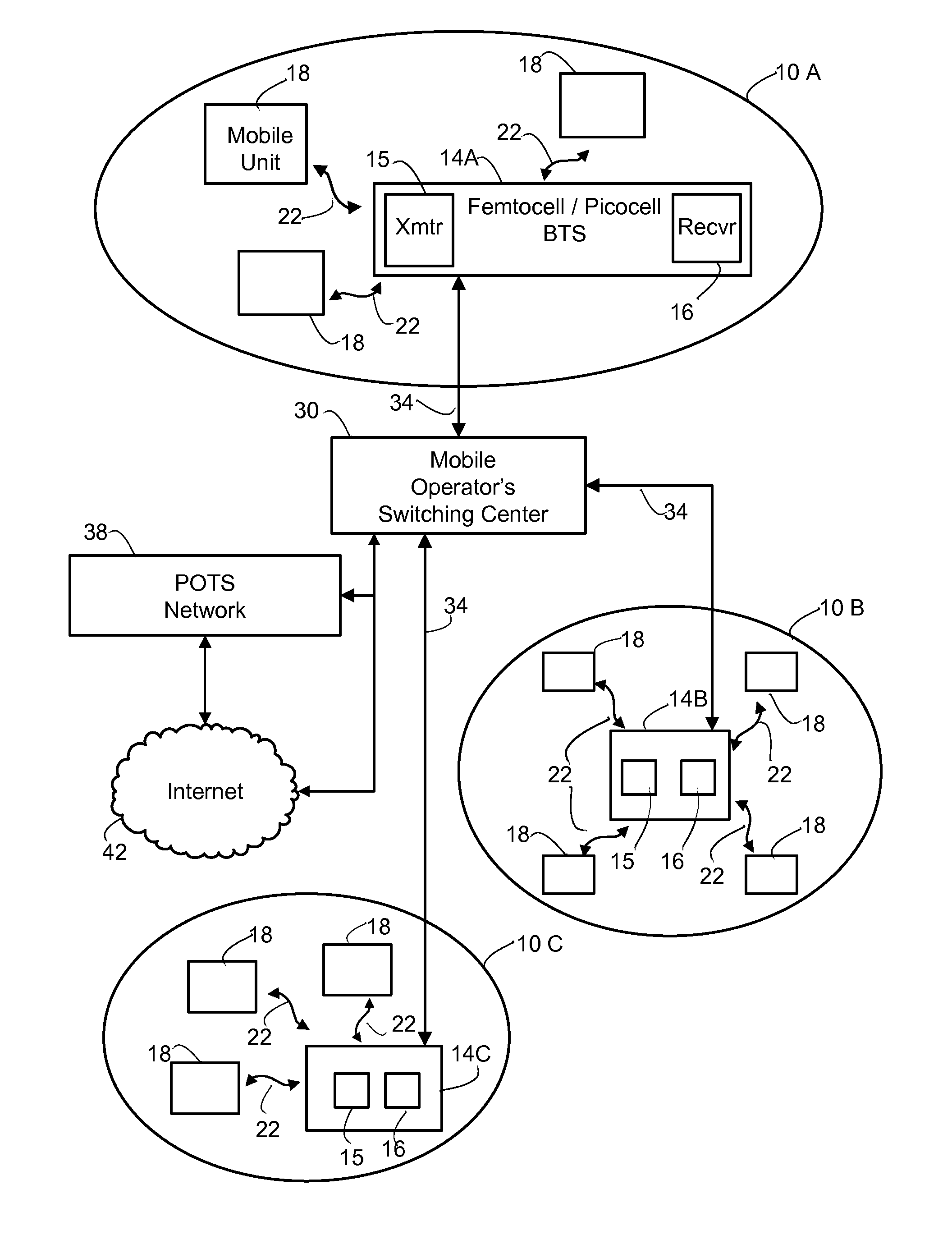
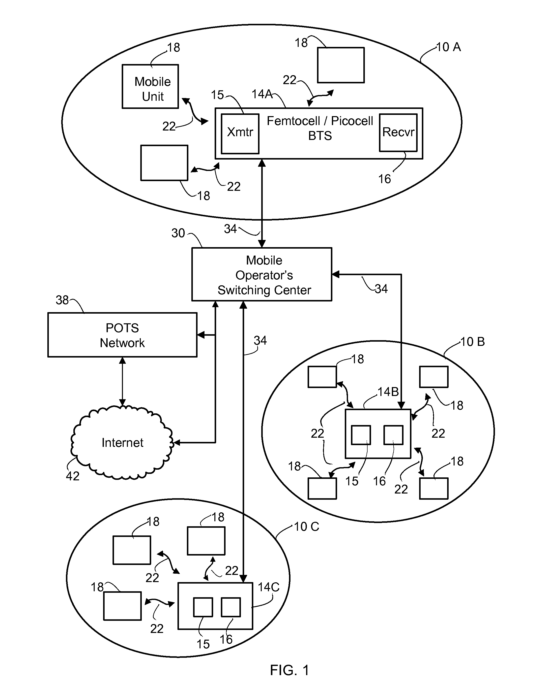
[0037]FIG. 1 illustrates several femtocell / picocell coverage areas 10A, 10B and 10C and a femtocell / picocell base transceiver ...


PUM


Abstract

A method for determining whether to reconfigure a self-organizing network (SON) comprising coverage areas each having a BTS and an antenna and mobile units operating in each coverage area. The method comprises: at each BTS, scanning an antenna beam, measuring performance data, and determining whether measured performance data indicates a network reconfiguration; if a result is negative, at a first BTS returning to the step of scanning the antenna beam; if the result is affirmative, selecting one or more of reconfiguring the SON by changing the RF output power of the first BTS, changing an antenna beam pattern of the antenna at the first BTS, changing an antenna tilt angle of the antenna at the first BTS, changing an operating frequency of the first BTS and updating a proximate cell site list of the first BTS.

Description

CROSS-REFERENCE TO RELATED APPLICATIONS[0001]The present application claims priority to a provisional application entitled Self-Organizing Networks within Picocell and Femtocell Network Coverage Areas Using Directional Beam Antennas, filed on Jul. 13, 2009 and assigned application No. 61 / 224,977. The contents of the provisional application are hereby incorporated by reference.FIELD OF THE INVENTION[0002]The present invention relates to wireless communications networks, femtocells, smart antennas, and interference mitigation.BACKGROUND OF THE INVENTION[0003]A femtocell / picocell network comprises a relatively small radio coverage area (wireless) with a base station for receiving signals from and sending signals to mobile units within the femtocell coverage area. The femtocell / picocell networks are typically deployed as either a residential or an enterprise in-building wireless network. The base station is generally a fully-featured but low-power mobile phone base station and is connec...

Claims


Application Information

Patent Timeline
IPC IPC(8): H04M3/00H04W72/00
CPCH01Q9/0407H04W84/045H01Q13/10H01Q19/30H04B7/0408H04B7/0632H04B7/0695H04B7/088H04W16/28H04W24/02H04W24/08H04W52/143H04W52/241H04W52/243H01Q13/08
Inventor LEE, JUNGWOOPARK, SEYONG
Owner LEE JUNGWOO
Learn More