
Power output apparatus and movable body with power output apparatus mounted thereon

a technology of power output and movable body, which is applied in the direction of process and machine control, hybrid vehicles, instruments, etc., can solve the problems of not being able to adequately handle the situation of a relatively large load, the vehicle speed may significantly exceed the preset level, and the working status of the control system

Inactive Publication Date: 2005-06-07
TOYOTA JIDOSHA KK
View PDF19 Cites 22 Cited by
  • Summary
  • Abstract
  • Description
  • Claims
  • Application Information

AI Technical Summary

Benefits of technology

[0006]The object of the present invention is thus to provide a power output apparatus that certainly keeps the revolving speed of a drive shaft at a preset level. The object of the invention is also to certainly keep the travelling speed of a movable body with the power output apparatus mounted thereon at a preset level.
[0009]The power output apparatus of the invention sets a wider power output range, in response to setting of a revolving speed, than a possible power output range according to the accelerator opening, and drives and controls the power output unit to keep the revolving speed of the drive shaft at the preset revolving speed by output of a power in the preset power output range. The arrangement of setting the wider power output range in response to setting of the revolving speed than the possible power output range according to the accelerator opening enables a power to be output to the drive shaft corresponding to each of diverse loads applied to the drive shaft. This arrangement enables the revolving speed of the drive shaft to be certainly kept at the preset revolving speed. Here the ‘power’ includes a negative power, that is, a braking force.
[0012]The movable body of the invention sets a wider power output range, in response to setting of a travelling speed, than a possible power output range according to the accelerator opening, and drives and controls the power output unit to keep the travelling speed at the preset travelling speed by output of a power in the preset power output range. The arrangement of setting the wider power output range in response to setting of the travelling speed than the possible power output range according to the accelerator opening enables a power to be output to the drive shaft corresponding to each of diverse loads applied to the drive shaft. This arrangement enables the travelling speed to be certainly kept at the preset travelling speed. Here the ‘power’ includes a negative power, that is, a braking force.
[0015]The method of the invention sets a wider power output range, in response to setting of a revolving speed, than a possible power output range according to the accelerator opening, and drives and controls the power output unit to keep the revolving speed of the drive shaft at the preset revolving speed by output of a power in the preset power output range. The arrangement of setting the wider power output range in response to setting of the revolving speed than the possible power output range according to the accelerator opening enables a power to be output to the drive shaft corresponding to each of diverse loads applied to the drive shaft. This arrangement enables the revolving speed of the drive shaft to be certainly kept at the preset revolving speed. Here the ‘power’ includes a negative power, that is, a braking force.

Problems solved by technology

The cruise control system in a working status, on the other hand, may not sufficiently handle the situation of a relatively large load applied to an axle, for example, during a drive on a steep slope, and fail to keep the vehicle speed at the preset level.
While the vehicle runs on a relatively steep downslope, the vehicle speed may significantly exceed the preset level due to an insufficient braking force output to the axle.

Method used


Image

  • Power output apparatus and movable body with power output apparatus mounted thereon
  • Power output apparatus and movable body with power output apparatus mounted thereon
  • Power output apparatus and movable body with power output apparatus mounted thereon

Examples


Embodiment Construction

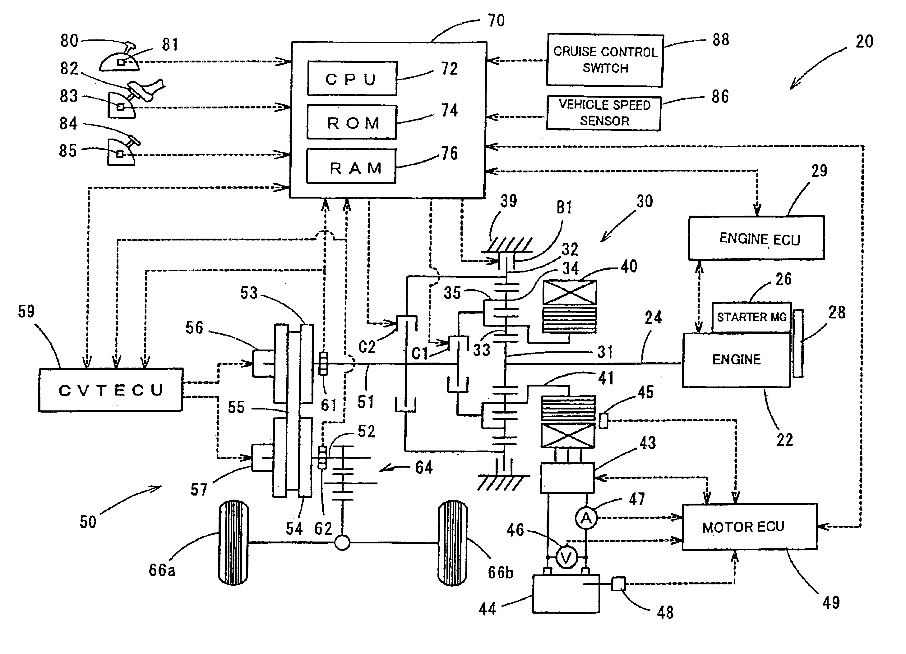
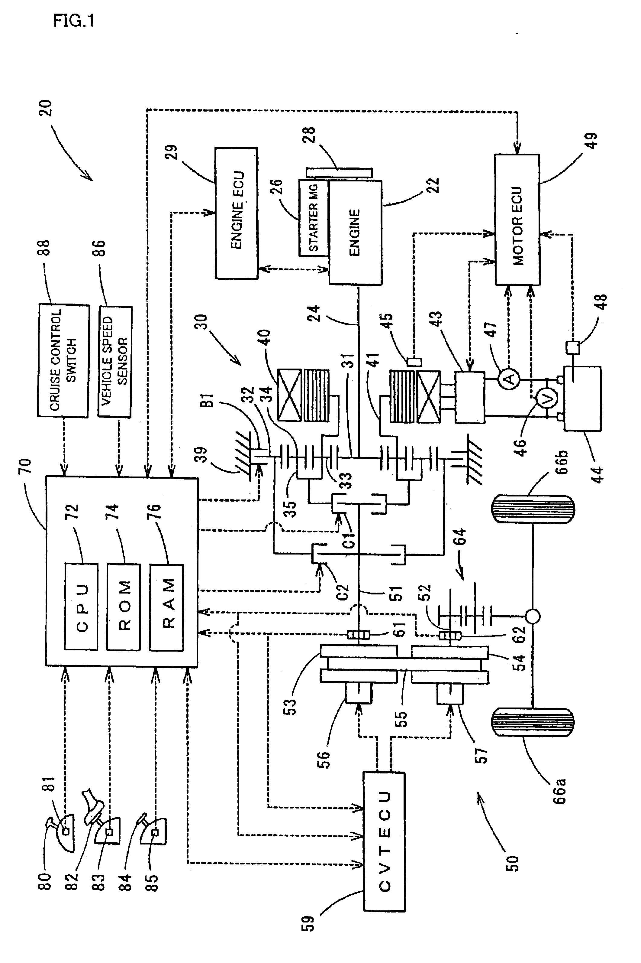
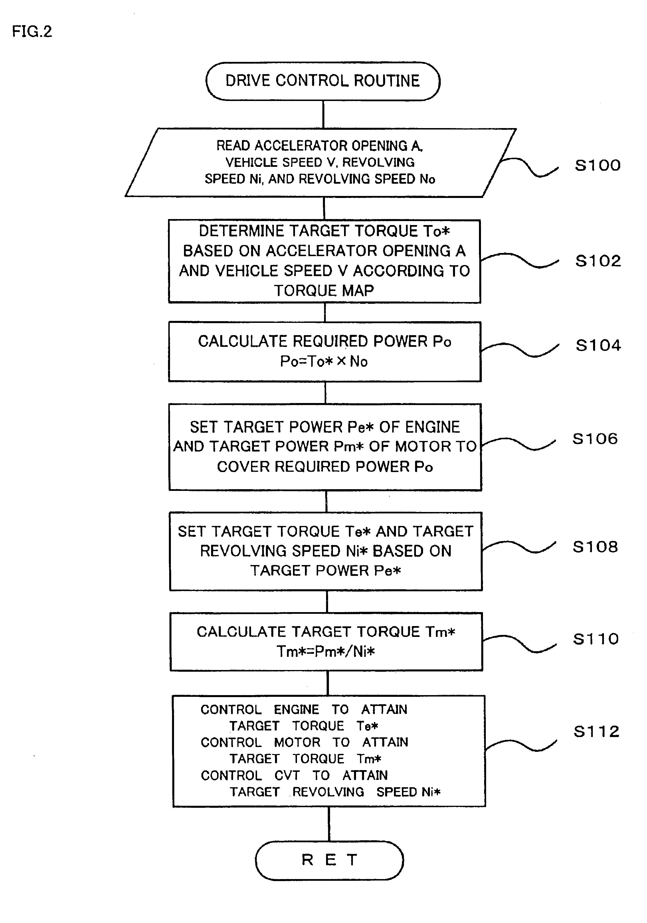
[0022]One mode of carrying out the invention is discussed below as a preferred embodiment. FIG. 1 schematically illustrates the construction of a power output apparatus 20 in one embodiment of the present invention. The power output apparatus 20 of the embodiment is constructed to output power, for example, to driving wheels of a hybrid vehicle. The power output apparatus 20 includes an engine 22, a planetary gear unit 30 linked with a crankshaft 24 i.e. an output shaft of the engine 22, a motor 40 connected with the planetary gear unit 30 for power generation, a CVT 50 as a continuously variable transmission connected with the planetary gear unit 30 and coupled with driving wheels 66a and 66b via a differential gear 64, and a hybrid electronic control unit (hereafter referred to as hybrid ECU) 70 for controlling the respective constituents of the whole power output apparatus 20.

[0023]The engine 22 is an internal combustion engine that uses a hydrocarbon fuel, such as gasoline or li...


PUM


Abstract

The technique of the invention sets a relationship between the throttle opening (corresponding to the accelerator opening), the vehicle speed, and the target torque of a drive shaft, so as to enable a greater braking torque to be output in a working status of a cruise control system than a braking torque, which is output to the drive shaft in a full closed position of the accelerator opening in a non-working status of the cruise control system. This arrangement ensures output of a sufficient braking force to the drive shaft even under the condition of a relatively large drive load applied to the drive shaft, for example, during a downslope run, thus enabling the vehicle speed to be certainly kept at a preset level under the control of the cruise control system.

Description

BACKGROUND OF THE INVENTION[0001]1. Field of the Invention[0002]The present invention relates to a power output apparatus and a movable body with a power output apparatus mounted thereon.[0003]2. Description of the Prior Art[0004]A type of proposed power output apparatus has a constant speed control system that keeps the revolving speed of a drive shaft at a preset level (for example, JAPANESE PATENT LAID-OPEN GAZETTE No. 1-114547). A cruise control system mounted on an automobile, for example, automatically regulates, in response to a driver's setting of a desired vehicle speed, the throttle opening of an engine without any operation of an accelerator pedal, so as to keep the vehicle speed at a preset level.[0005]In a non-working status of the cruise control system, the driver can operate an accelerator pedal and a brake pedal according to the conditions of a road or another driving path (that is, the loading applied to wheels), for example, a slope, to regulate the vehicle speed t...

Claims


Application Information

Patent Timeline
Patent Type & Authority Patents(United States)
IPC IPC(8): B60K31/04B60K6/04B60K31/02B60K6/00B60K1/02B60K1/00F16H61/662F16H61/66B60W20/00B60K6/48B60K31/00B60L7/24B60L50/16B60W10/02B60W10/04B60W10/06B60W10/08B60W10/10B60W10/11B60W10/18F02D29/02F02D29/06
CPCB60K6/48B60K6/543B60K31/04B60W10/02B60W10/06B60W10/08B60W20/00B60K6/365B60K1/02Y10T477/26B60L2240/486B60W2520/10B60W2540/10B60W2540/12B60W2540/16F16H61/662F16H2061/6612Y02T10/6221Y02T10/6286Y02T10/7258Y10S903/945Y10S903/946Y10S903/91Y10S903/947Y10S903/918Y10T477/6223Y10T477/23Y10T477/69Y10T477/676Y10T477/619Y02T10/62Y02T10/72B60K2006/268B60W10/18B60W20/13
Inventor KAMICHI, KENSUKEOBA, HIDEHIRO
Owner TOYOTA JIDOSHA KK
Learn More