Electromagnetic load drive apparatus

a technology of load drive and load, which is applied in the direction of electric control, magnetic bodies, pulse techniques, etc., can solve the problems of insufficient replenishment of energy and inability to increase the voltage across the terminals of capacitive elements, and achieve the effect of reducing the amount of energy recovered and easy recovery of energy

Inactive Publication Date: 2005-05-31
DENSO CORP
View PDF8 Cites 11 Cited by
  • Summary
  • Abstract
  • Description
  • Claims
  • Application Information

AI Technical Summary

Benefits of technology

[0009]It is an object of the present invention to provide an electromagnetic load drive apparatus that attains a quick response to a sufficient degree.
[0011]Further, the inductive element accumulates the energy of an amount greater, by the voltage across the terminals of the low voltage power source, than that of the energy held by the capacitive element at the start of operation of the inductive element, and avoids a large decrease in the amount of energy recovered by the capacitive element as compared to the value at the start of operation of the electromagnetic load. Therefore, the response does not drop even when the interval is short until the next operation of the electromagnetic load. When the operation of the inductive element is discontinued, the potential of the capacitive element is brought close to the reference voltage as compared to that of during the operation, and energy can be easily recovered from the inductive element.
[0012]Preferably, even when the capacitive element of a small capacity is employed to elevate the voltage across the terminals, the electric current can be supplied to a sufficient degree by using an assisting capacitive element even after the voltage across the terminals of the capacitive element has sharply dropped. As a result, energy is accumulated to a sufficient degree in the inductive element, and the voltage across the terminals of the capacitive element after having recovered the energy can be easily recovered up to a voltage at the start of the electromagnetic load operation.

Problems solved by technology

From the breakdown voltage of the capacitive element, however, it is not allowed to increase the voltage across the terminals of the capacitive element.
However, the energy cannot be sufficiently replenished when the interval is short until the next operation of the actuator.

Method used


Image

  • Electromagnetic load drive apparatus
  • Electromagnetic load drive apparatus
  • Electromagnetic load drive apparatus

Examples


first embodiment

[0025](First Embodiment)

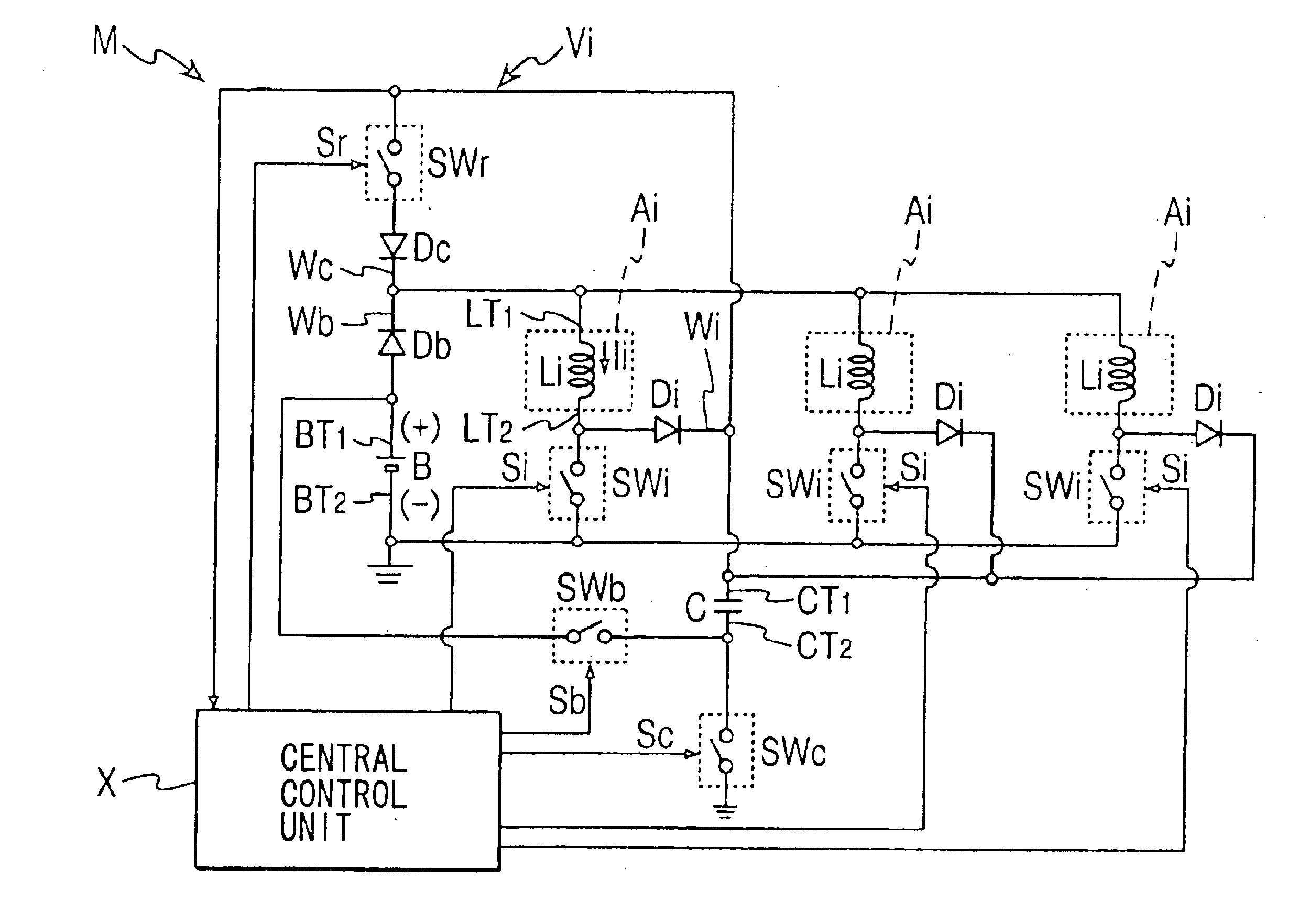
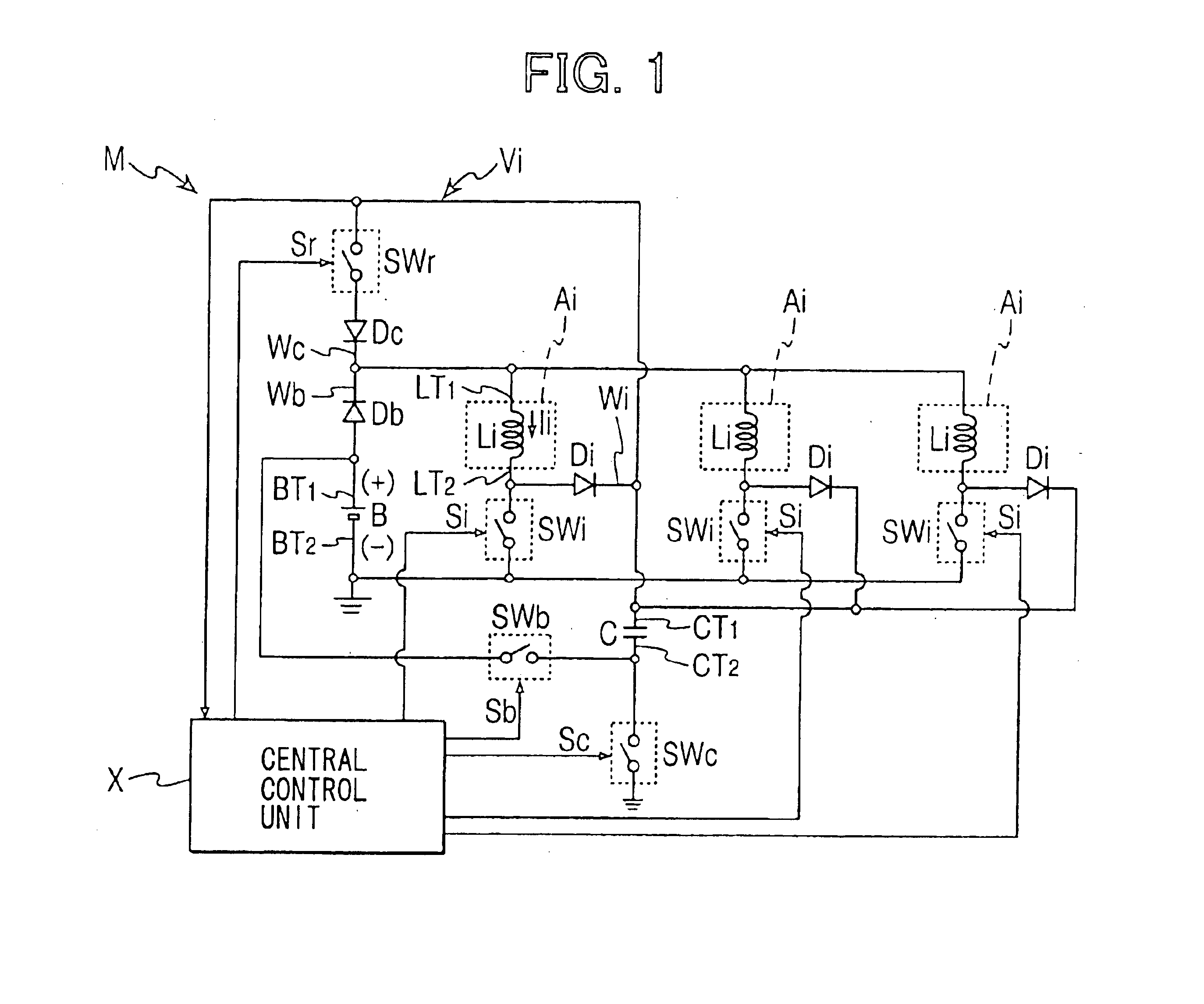
[0026]Referring first to FIG. 1 illustrating an electromagnetic load drive apparatus, an electromagnetic load drive apparatus M is common to a plurality of electromagnetic loads Ai, and selectively drives the electromagnetic loads Ai. Its example can be represented by a fuel injector of a MPI system used for internal combustion engines. Namely, in the internal combustion engine, an injector which is an electromagnetic load for injecting fuel is provided for each of the cylinders, and a solenoid which is an inductive element included in the injector changes the valve inserted in the nozzle of the injector between a seated state and a lifted state upon changing over the electromagnetic attractive force to thereby change over the fuel injection and fuel interruption. In the first embodiment, three electromagnetic loads Ai are provided for a three-cylinder internal combustion engine.

[0027]The electromagnetic loads Ai have solenoids Li corresponding to each of the...

second embodiment

[0045](Second Embodiment)

[0046]As shown in FIG. 3, an electromagnetic load drive apparatus M according to a second embodiment is constructed in the similar manner as the first embodiment. In the first embodiment, the recovery of energy when the operation is stopped is completed as the voltage Vc across the terminals of the capacitor C assumes the predetermined end voltage. According to the second embodiment, however, the operation characteristics of the electromagnetic load Ai can be further improved.

[0047]The central control unit X receives the capacitor potential Vi as well as the positive side potential (=voltage Vb across the terminals of the battery) of the battery B, and sets a period for completing the charging of the capacitor C based on the capacitor potential Vi and the voltage Vb across the terminals of the battery B.

[0048]That is, the central control unit X sets the end voltage of the capacitor potential Vi (=voltage Vc across the terminals of the capacitor) so that the ...

third embodiment

[0051](Third Embodiment)

[0052]As shown in FIG. 5, an electromagnetic load drive apparatus M according to a third embodiment is constructed in the similar manner as the second embodiment.

[0053]In the third embodiment, the central control unit X sets the timing for completing the charging of the capacitor C based on the capacitor potential Vi and the voltage Vb across the terminals of the battery B.

[0054]That is, the central control unit X sets the end voltage of the capacitor potential Vi (=voltage Vc across the terminals of the capacitor C) so that the sum (Vb+Vc) of the voltage Vb across the terminals of the battery B and the voltage Vc across the terminals of the capacitor C assumes a predetermined value Vs.

[0055]That is, the central control unit X sets the end voltage of the capacitor potential Vi (=voltage Vc across the terminals of the capacitor C) so that the sum (Vb+Vc) of the voltage Vb across the terminals of the battery B and the voltage Vc across the terminals of the capa...


PUM

PropertyMeasurementUnit
voltageaaaaaaaaaa
electric poweraaaaaaaaaa
end voltageaaaaaaaaaa

Abstract

A drive apparatus supplies electric power to a solenoid of an inductive load from a battery and a capacitor to improve response of the load. The drive apparatus comprises switches for switching between a first state where a negative side of the battery is connected to a positive side of the battery, and a second state where the negative side of the capacitor is connected to the negative side of the battery. When the load is in operation, the voltage applied to the solenoid is raised by the voltage of the battery as the first state, so that the current flowing into the solenoid rises sharply to improve response of the load. When the operation of the load is to be stopped, the electric power to the solenoid is interrupted, and the energy accumulated in the solenoid is recovered by the capacitor as the second state.

Description

CROSS REFERENCE TO RELATED APPLICATION[0001]This application is based on and incorporates herein by reference Japanese Patent Application No. 2002-366060 filed on Dec. 18, 2002.FIELD OF THE INVENTION[0002]This invention relates to an electromagnetic load drive apparatus.BACKGROUND OF THE INVENTION[0003]A variety of actuators are in practical use for producing a driving force by flowing an electric current into an inductive element such as a solenoid and varying the electromagnetic state. In an internal combustion engine, for example, such an actuator is mounted on an injector that injects fuel, and drives the valve of the injector.[0004]A drive apparatus for driving the electromagnetic load having the inductive element includes a capacitor as a capacitive element in addition to a battery which is a DC low voltage power source. In this apparatus, the energy accumulated in the inductive element due to the supply of electric power is recovered by the capacitive element by generating a ...

Claims


Application Information

Patent Timeline
Patent Type & Authority Patents(United States)
IPC IPC(8): F02D41/20F02M51/00F02M51/06H01F7/18
CPCF02D41/20H01F7/1816F02D2041/2006H01F2007/1822H01F7/1877
Inventor TOJO, SENTAYODA, TOSHIYUKIKATO, KEIICHI
Owner DENSO CORP
Why Eureka
Try Eureka