
Submersible light-directing member for material excitation in microfluidic devices

a microfluidic device and light-directing member technology, applied in fluorescence/phosphorescence, optical radiation measurement, laboratory glassware, etc., can solve the problems of imposing difficult demands on chip flatness or dimensional tolerance, adversely affecting sample detection capabilities, and affecting sample detection performance. , to achieve the effect of reducing interferen

Inactive Publication Date: 2005-05-31
MONOGRAM BIOSCIENCES
View PDF7 Cites 115 Cited by
  • Summary
  • Abstract
  • Description
  • Claims
  • Application Information

AI Technical Summary

Benefits of technology

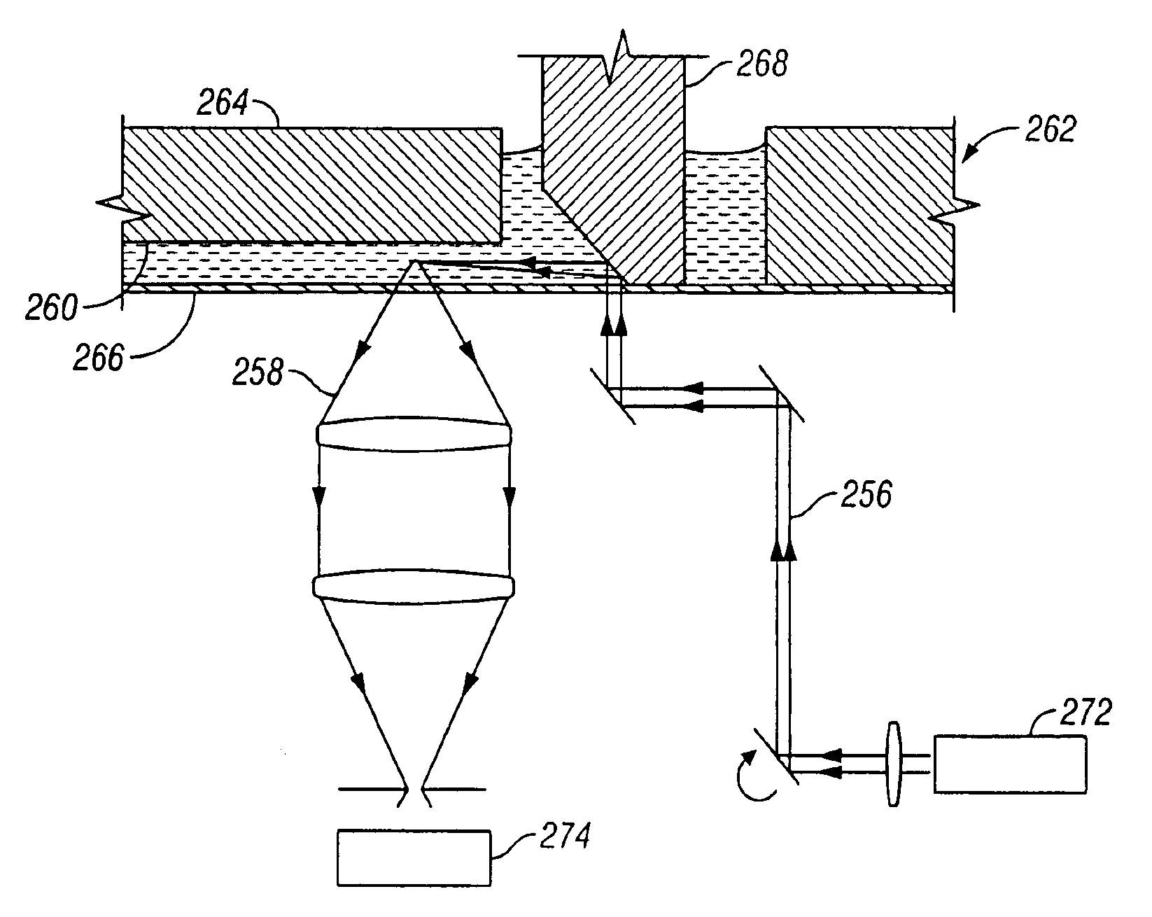
[0011]In one variation, the system includes a light directing member, a light source, and one or more movable reflectors positioned in the optical path of the light. By adjusting the angle of the reflector(s), the excitation beam may be selectively sent to a channel or a target region of a channel. The excitation beam is desirably sent through the vertical center of the channel in order to reduce interference arising from light reflecting of the channel walls. The reflector may be held by a rotational actuator such as a galvanometer.

Problems solved by technology

Irrespective of what advantages such systems provide, they suffer from serious drawbacks.
Background illumination or scattering of light introduced at detection windows and less-than-perfect reflecting surfaces often adversely affect sample detection capabilities.
Some configurations impose difficult demands on chip flatness or dimensional tolerances.
This may introduce background fluorescence (i.e., autofluorescence) that also decreases detection signal accuracy.
Again, autofluorescence is problematic because it decreases detection sensitivity.
Issues associated with cost and reproducibility are presented in either case.

Method used


Image

  • Submersible light-directing member for material excitation in microfluidic devices
  • Submersible light-directing member for material excitation in microfluidic devices
  • Submersible light-directing member for material excitation in microfluidic devices

Examples


Embodiment Construction

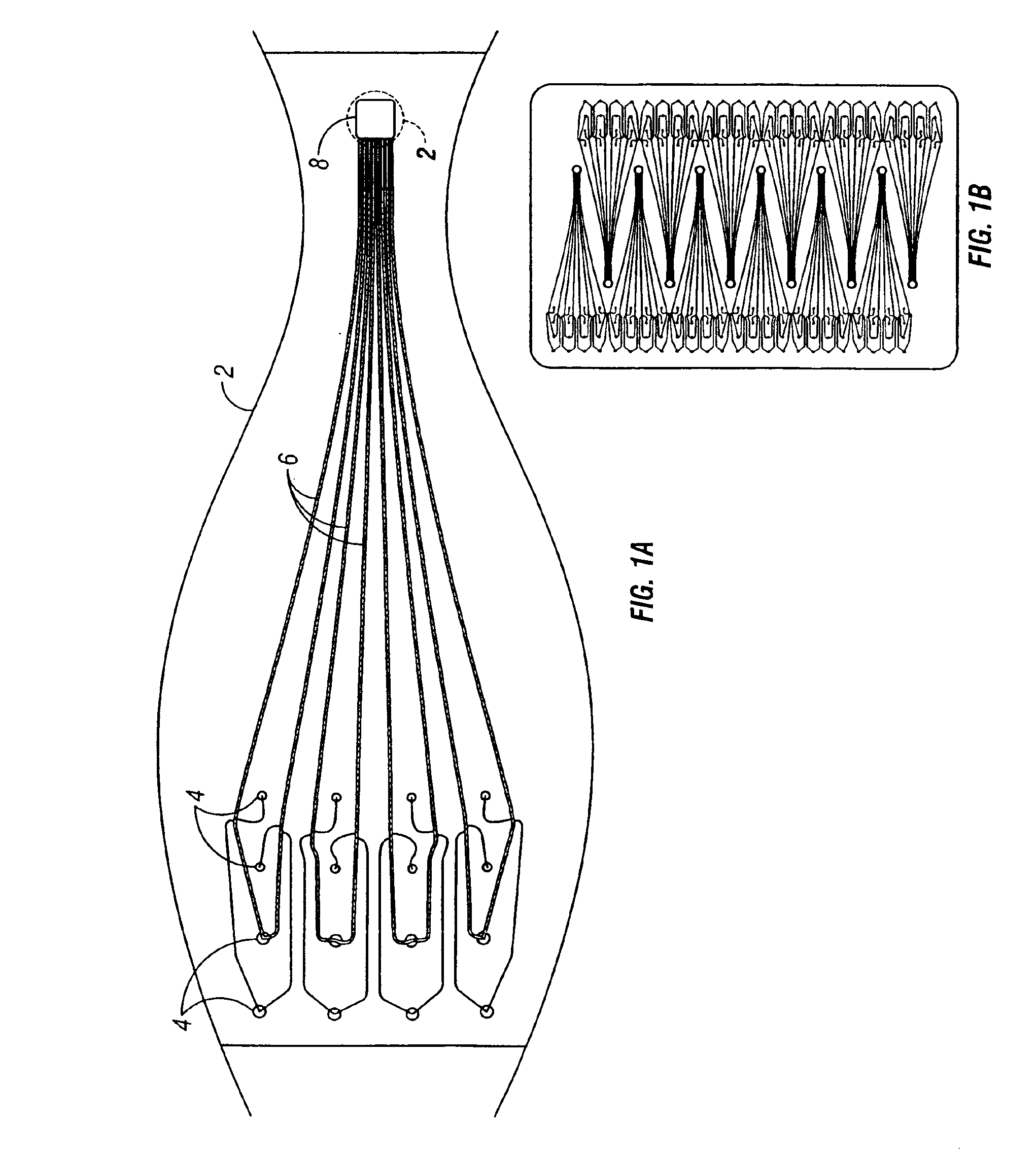
[0035]In connection with the figures, the following text provides examples or variations of the invention. Turning to FIG. 1A, a portion of a chip (2) is shown. It includes a plurality of ingress reservoirs (4) in communication with a plurality of channels (6) which exit into a common waste well (8). Samples reagents added to selected ingress reservoirs are electrokinetically manipulated to carry out various processes as noted above.

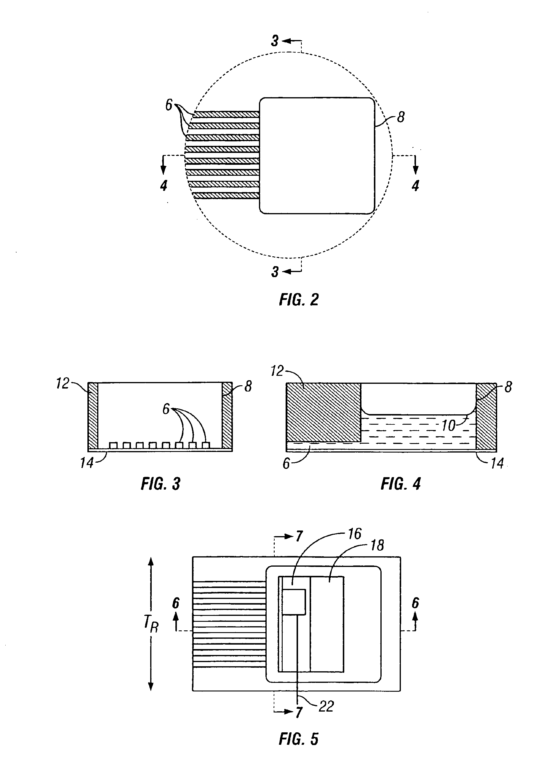
[0036]FIG. 2 shows a detail of the chip in the area of the waste well. Multiple channels (6) empty into well (8). FIG. 3 shows the channels end-on as they enter the well. FIG. 4 shows a channel and the well in cross section, with the well partially filled with liquid to form a meniscus (10).

[0037]FIGS. 3 and 4 both illustrate a preferred manner of producing chip (2). A chip body (12) defines a portion of each of the aforementioned features, with a base backing or covering (14) affixed thereto that completes the channels and reservoirs / wells.

[0038]The mic...


PUM


Abstract

A system for material excitation in microfluidic devices is described. Aspects of the invention resemble a submerged periscope when in use. They allow for light to be redirected along a more advantageous trajectory as does the maritime device. A prism with a reflecting surface may be used to direct a laser beam along one or more microfluidic trenches or channels. Alternatively, a reflecting surface may be provided in connection with a simple support. Directing a beam along multiple paths is preferably accomplished by scanning a single laser across or around the reflecting surface provided. Provision may be made for at least a portion of the submersible used to function as an electrode to assist in electrokinetically driving fluids and / or ions within the microfluidic device.

Description

CROSS-REFERENCE TO RELATED APPLICATIONS AND PATENTS[0001]This application is a continuation of and claims priority to International application PCT / US02 / 19494 filed Jun. 19, 2002, which claims priority to U.S. provisional application Ser. No. 60 / 305,122, filed Jul. 12, 2001, which applications are each incorporated herein by reference in its entirety.TECHNICAL FIELD[0002]This relates to systems for detection of material in microfluidic devices. Aspects of the invention provide for direct application of light to excite material within a device to enable fluorescent detection without producing background fluorescence in a chip resulting in signal loss or interference.BACKGROUND[0003]In performing any one of several useful types of analyses, microfluidic devices may be employed. Whether applied for the purpose of DNA separation or drug screening, the ability to achieve movement of sample, reagents and buffer within a network of fine trenches or channels can result is great time savings...

Claims


Application Information

Patent Timeline
IPC IPC(8): B01L3/00G01N21/85G01N21/05G01N21/64G01N27/447
CPCB01L3/502715G01N21/05G01N21/6428G01N21/645G01N27/44721G01N27/44791G01N21/8507B01L2300/0654B01L2300/0816G01N2021/0346G01N2021/058G01N2021/6439G01N2021/6467G01N2021/6482
Inventor BJORNSON, TORLEIF O.MAHER, KEVINGLUSZCAK, MICHAEL ROBERT
Owner MONOGRAM BIOSCIENCES
Learn More