Lash adjuster for valve actuator

a technology of actuator and lash, which is applied in the direction of valve drive, valve details, valve arrangement, etc., can solve the problems of insufficient ruggedness of contact surfaces, insufficient efficiency of oil film discharge, and inability to push up the adjuster screw any further, etc., to achieve sufficient friction coefficient, stabilize the valve lift, and reduce the effect of friction

Inactive Publication Date: 2005-05-31
NTN CORP
View PDF5 Cites 2 Cited by
  • Summary
  • Abstract
  • Description
  • Claims
  • Application Information

AI Technical Summary

Benefits of technology

[0025]In either invention, oil film can be quickly expelled from between the opposed pressure flanks from the time when a distance is present between the pressure flanks to the time when they contact each other.
[0026]The rugged surfaces formed on the pressure flanks divided circumferentially into small sections keep sufficient roughness and thus a frictional coefficient sufficient to prevent the adjuster screw from being pushed into the threaded hole while turning, even if the pressure flanks get worn with prolonged use. This stabilizes the valve lift.

Problems solved by technology

Once the play disappears, the adjuster screw cannot be pushed up any further because the frictional force between the pressure flanks is large.
The lash adjuster disclosed in either of the abovementioned Japanese publications has one problem that when the pressure flanks of the female and male threads are abraded and get worn, the contact surfaces tend to become smooth.
This reduces friction between the pressure flanks to such an extent as not to be able to check the rotation of the adjuster screw.
But ruggedness formed by such rough surfaces are not sufficient to efficiently discharge oil film.
Especially in a low-temperature condition in which the viscosity of lubricating oil becomes high, it takes time to expel oil and thus the adjuster screw can slip and turn, so that the valve lift decreases.
Thus, if the pressure flanks become smooth due to wear, the distance therebetween before they contact decreases.
Thus, even if the pressure flanks are circumferentially divided into small sections, the load-bearing force of the oil film can grow rather large.

Method used


Image

  • Lash adjuster for valve actuator
  • Lash adjuster for valve actuator
  • Lash adjuster for valve actuator

Examples


Embodiment Construction

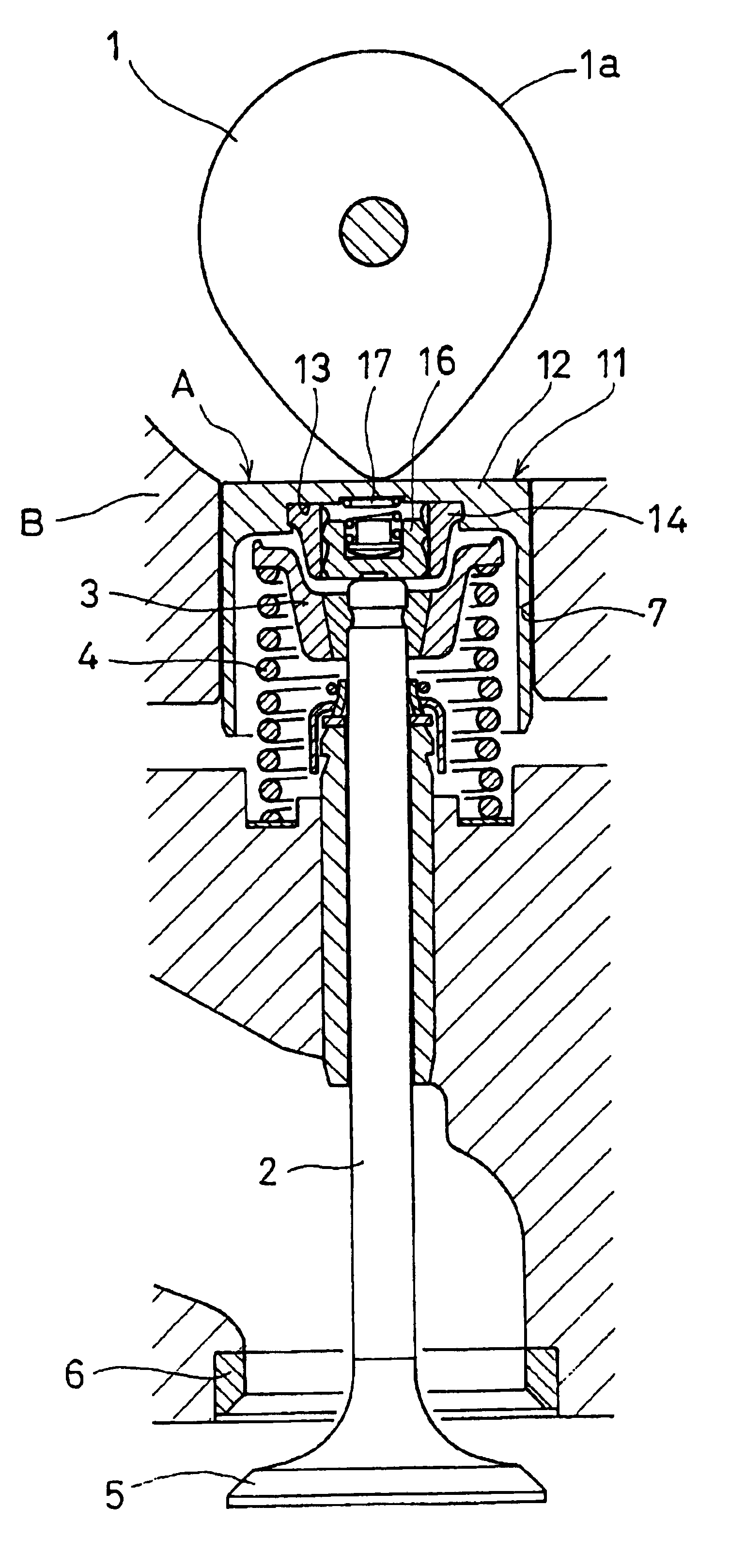
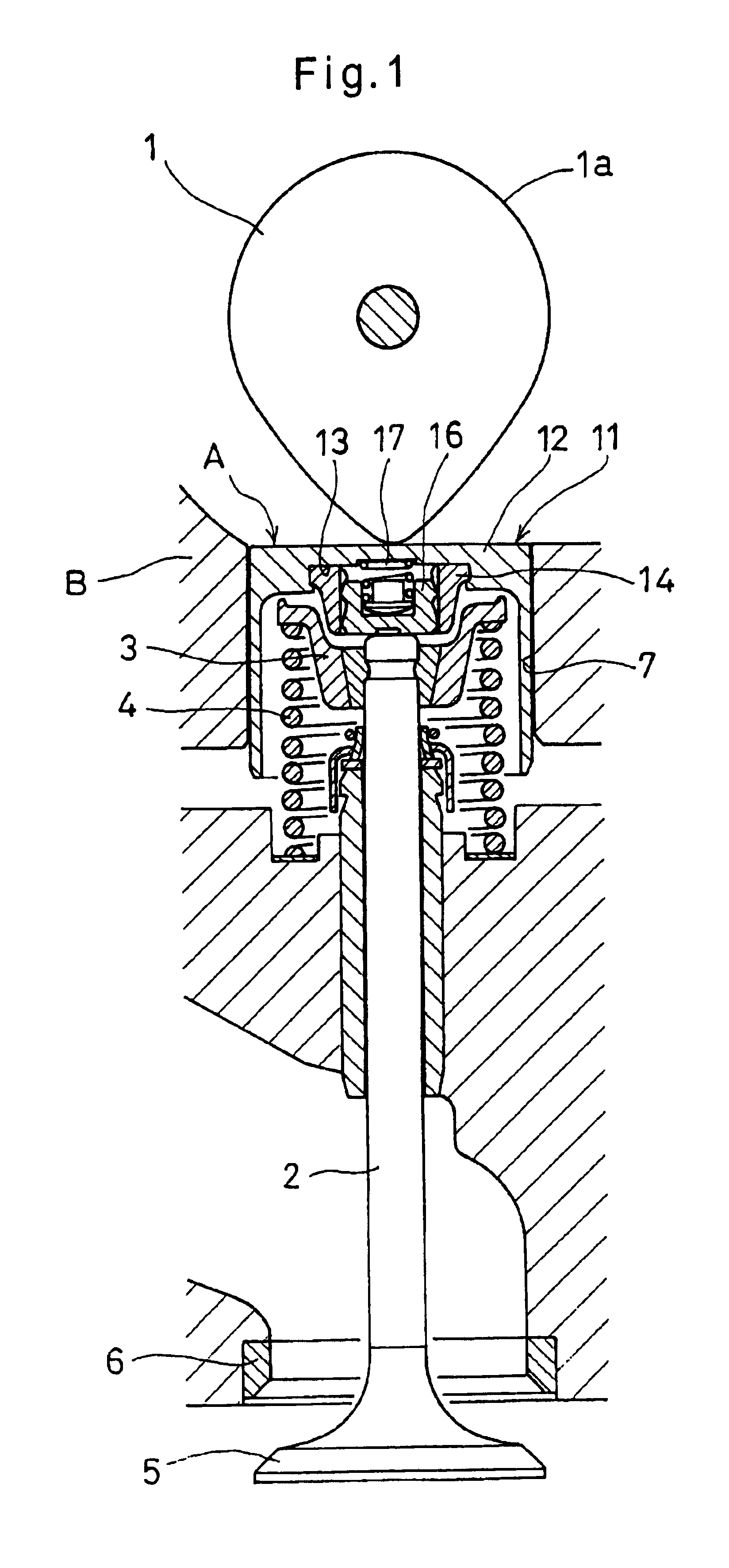
[0039]Now referring to the drawings, the lash adjuster embodying the present invention will be described. First referring to FIG. 1, the lash adjuster A embodying this invention is mounted between a cam 1 of a direct type valve actuator and a valve stem 2.

[0040]The valve stem 2 carries a spring retainer 3 at its top end. A valve spring 4 biases the spring retainer 3 and thus the valve stem 2 upwardly to keep a valve head 5 pressed against a valve seat 6.

[0041]As shown in FIG. 2, the lash adjuster A includes a lifter body 11. As seen in FIG. 1, the lifter body 11 is slidably mounted in a guide hole 7 formed in a cylinder head B. The lifter body 11 has an end plate 12 that is kept in contact with the cam 1. A recess 13 is formed in the bottom surface of the end plate 12. The lash adjuster A further includes a nut 14 having its upper portion received in the recess 13 of the lifter body 11. In this embodiment, the nut 14 is made integral with the lifter body 11 by caulking the edge of t...


PUM


Abstract

A lash adjuster is provided which can maintain stable valve lift. An adjuster screw is mounted into a threaded hole formed in the bottom of the end plate of a lifter body. An elastic member is mounted in the threaded hole to bias the adjuster screw axially downwardly. The female threads of the threaded hole and the male threads of the adjuster screw are serration-shaped. A plurality of axial grooves are formed in the inner periphery of the threaded hole to circumferentially divide the female threads into many separate portions, and satin-finished rough surfaces are formed on the pressure flanks of the male threads by shot-peening to enable quick expulsion of oil film disposed between the opposed pressure flanks, thereby stabilizing the valve lift.

Description

BACKGROUND OF THE INVENTION[0001]This invention relates to a lash adjuster for automatically adjusting the valve clearance in a valve actuator of an internal combustion engine.[0002]A valve actuator for opening and closing intake or exhaust valves (hereinafter simply “valves”) by rotating its cam includes a lash adjuster mounted between the cam and the valve to automatically adjust the valve clearance therebetween.[0003]U.S. Pat. No. 4,548,168 discloses such a lash adjuster which includes a lifter body having an end plate kept in contact with a cam and formed with a blind threaded hole in its bottom surface. An adjuster screw is in threaded engagement with the threaded hole and is biased axially by an elastic member mounted between the top end of the screw and the closed end of the threaded hole. The female threads of the threaded hole and the male threads of the adjuster screw are serration-shaped so that the pressure flank to which a push-in load applied to the adjuster screw is a...

Claims


Application Information

Patent Timeline
Patent Type & Authority Patents(United States)
IPC IPC(8): F01L1/02F01L1/20F01L1/14F01L1/22
CPCF01L1/02F01L1/22F01L1/143
Inventor EIJI, MAENOKEN, YAMAMOTO
Owner NTN CORP
Why Eureka
Try Eureka