
Control chip with multiple-layer defer queue

a control chip and defer queue technology, applied in computing, instruments, data conversion, etc., can solve the problems of reducing slowing down the operating speed of the system, and a single-layer defer queue cannot be processed, so as to reduce the amount of data flow between the cpu and the control chip, the overall performance of the system is improved, and the effect of reducing the amount of data flow

Inactive Publication Date: 2005-05-24
VIA TECH INC
View PDF3 Cites 0 Cited by
  • Summary
  • Abstract
  • Description
  • Claims
  • Application Information

AI Technical Summary

Benefits of technology

[0012]Accordingly, one object of the present invention is to provide a control chip having a multiple-layer defer queue and a method of operating the control chip so that a plurality of first type requests issued from a central processing unit (CPU) can be processed concurrently. Furthermore, the multiple-layer defer queue can support retry and defer transaction at the same time so that the amount of data flow between the CPU and the control chip is greatly reduced and overall performance of the system is improved.
[0014]In brief, the multiple-layer defer queue facilitates the simultaneous processing of a plurality of CPU requests belonging to the first request type. Furthermore, the multiple-layer defer queue also supports retry and defer transactions. Since the volume of data transmitted between the CPU and control chip is reduced, efficiency and overall performance of the system is greatly improved.

Problems solved by technology

However, the one-layered defer queue can only process one defer transaction that meets the defer conditions.
Hence, overall performance of the system decreases.
1. DFQ only has an one-layer when the DFQ is occupied, the CPU needs to repeatedly issue the request until the DFQ has space, due to the effect of retry. This slows down the operating speed of the system.
2. When the CPU issues a request belonging to the first type while the defer bit is still not enabled, due to that the DFQ of the control chip cannot store the first type request, the control chip will repeatedly issue retry response to the CPU. As a result, the CPU repeatedly issues the request to the control chip. This manner reduces the performance and efficiency of the whole system.

Method used


Image

  • Control chip with multiple-layer defer queue
  • Control chip with multiple-layer defer queue
  • Control chip with multiple-layer defer queue

Examples


Embodiment Construction

[0020]Reference will now be made in detail to the present preferred embodiments of the invention, examples of which are illustrated in the accompanying drawings. Wherever possible, the same reference numbers are used in the drawings and the description to refer to the same or like parts.

[0021]In the following embodiment, a two-layered defer queue is used as an example of the multiple-layer defer queue. However, anyone familiar with the technology knows that the invention is actually applicable to a multiple-layer defer queue having at least two layers.

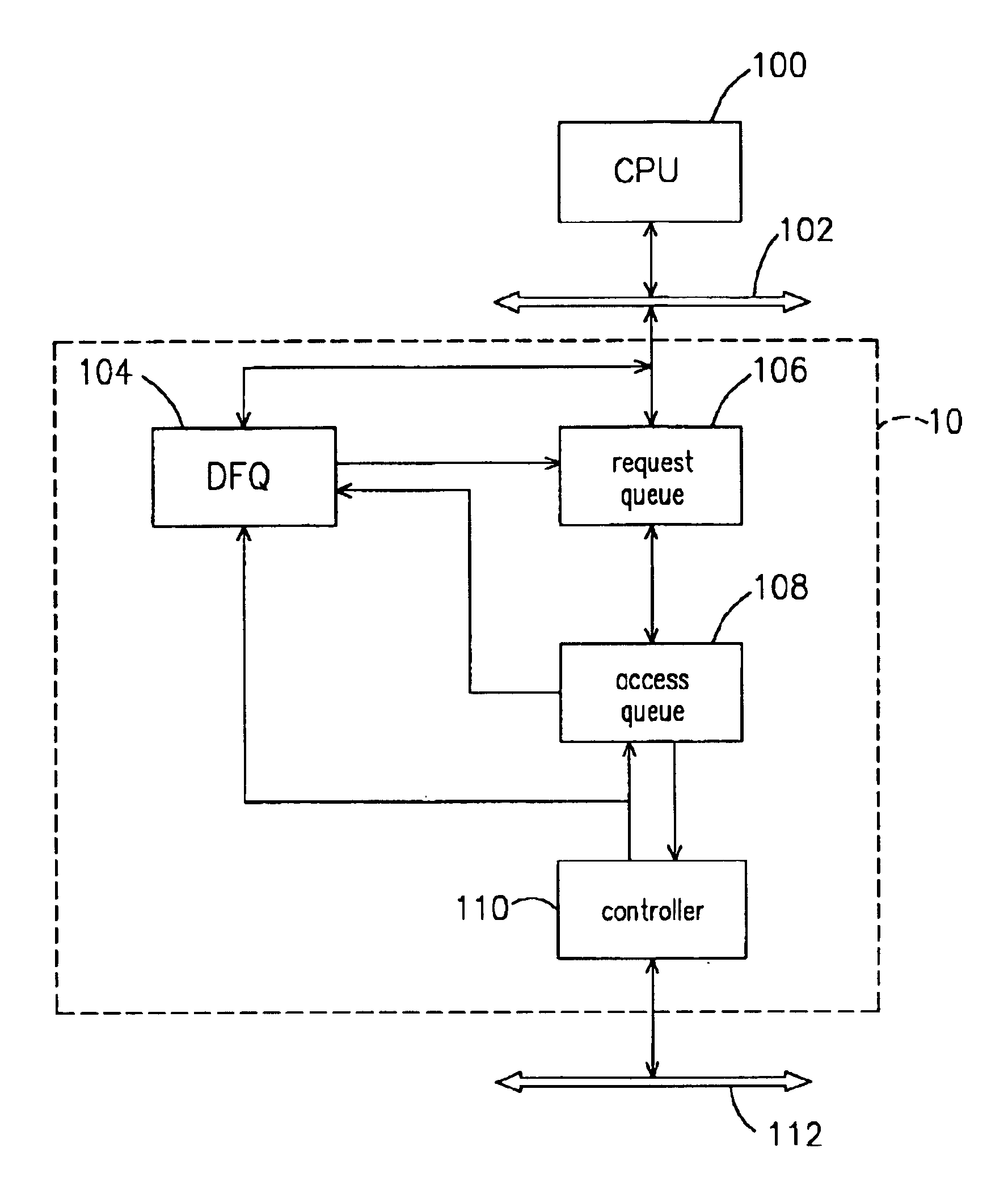
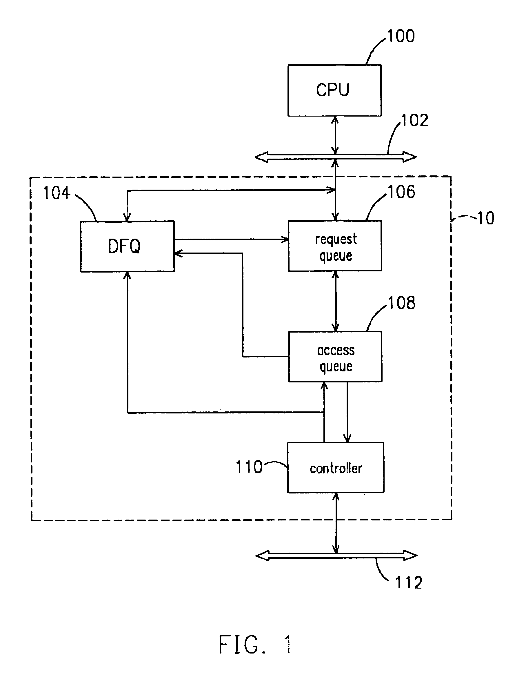
[0022]FIG. 1 is a block diagram showing a control chip having a multiple-layer defer queue therein according to one preferred embodiment of this invention. As shown in FIG. 1, the control chip 10 is coupled to a CPU bus 102 and a PCI bus 112. The control chip 10 at least includes a PCI request queue (PCQ) 106, a multiple-layer defer queue (DFQ) 104, a PCI access queue (PAQ) 108 and a PCI controller (PCIC) 110. The multiple-layer defer ...


PUM


Abstract

A control chip having a multiple-layer defer queue therein and a method of operating the control chip. The control chip is coupled to a CPU bus and a PCI bus. The control chip comprises of a PC request queue, a multiple-layer defer queue, a PCI access queue and a PCI controller. The multiple-layer defer queue facilitates the processing of a multiple of concurrent CPU requests that belong to a first request type. The multiple-layer defer queue supports retry and defer transactions, thereby reducing data transmission between the CPU and the control chip.

Description

CROSS REFERENCE TO RELATED APPLICATIONS[0001]This application claims the priority benefit of Taiwan application serial no. 90127631, filed on Nov. 7, 2001.BACKGROUND OF INVENTION[0002]1. Field of Invention[0003]The present invention relates to a control chip having a defer queue and a method of operating the control chip. More particularly, the present invention relates to control chip having a multiple-layer defer queue and a method of operating the control chip.[0004]2. Description of Related Art[0005]At present, personal computer has a central processing unit (CPU) that connects with a control chip through a high-speed CPU bus. The control chip is connected to an AGP bus and one or more PCI buses. The PCI buses may couple with a number of PCI compatible peripheral devices or memory units. Since the CPU is at the core of a personal computer, any requests from the CPU through the PCI bus must be processed quickly and do not affect other requests demanded by the CPU are unaffected. ...

Claims


Application Information

Patent Timeline
IPC IPC(8): G06F12/00G06F13/40
CPCG06F13/4059
Inventor WU, SHENG-CHUNGCHIU, YOU-MING
Owner VIA TECH INC
Learn More